Every problem in the chapter beside the book’s answer, a chapter at a time as you scroll.

Chapter 10: Direct-Current Circuits

58 problems · 24 figures

Check Your Understanding 10.1 §10.1 source ↗

If you place a wire directly across the two terminal of a battery, effectively shorting out the terminals, the battery will begin to get hot. Why do you suppose this happens?

Answer

If a wire is connected across the terminals, the load resistance is close to zero, or at least considerably less than the internal resistance of the battery. Since the internal resistance is small, the current through the circuit will be large, I= εR+r= ε0+r= εr. The large current causes a high power to be dissipated by the internal resistance (P=I2r). The power is dissipated as heat.

Check Your Understanding 10.2 §10.2 source ↗

Some strings of miniature holiday lights are made to short out when a bulb burns out. The device that causes the short is called a shunt, which allows current to flow around the open circuit. A “short” is like putting a piece of wire across the component. The bulbs are usually grouped in series of nine bulbs. If too many bulbs burn out, the shunts eventually open. What causes this?

Answer

The equivalent resistance of nine bulbs connected in series is 9R. The current is I=V/9R. If one bulb burns out, the equivalent resistance is 8R, and the voltage does not change, but the current increases (I=V/8R). As more bulbs burn out, the current becomes even higher. Eventually, the current becomes too high, burning out the shunt.

Check Your Understanding 10.3 §10.2 source ↗

Consider the same potential difference (V=3.00V) applied to the same three resistors connected in series. Would the equivalent resistance of the series circuit be higher, lower, or equal to the three resistor in parallel? Would the current through the series circuit be higher, lower, or equal to the current provided by the same voltage applied to the parallel circuit? How would the power dissipated by the resistor in series compare to the power dissipated by the resistors in parallel?

Answer

The equivalent of the series circuit would be Req= 1.00Ω+ 2.00Ω+ 2.00Ω= 5.00Ω, which is higher than the equivalent resistance of the parallel circuit Req=0.50Ω. The equivalent resistor of any number of resistors is always higher than the equivalent resistance of the same resistors connected in parallel. The current through for the series circuit would be I= 3.00V5.00Ω= 0.60A, which is lower than the sum of the currents through each resistor in the parallel circuit, I=6.00A. This is not surprising since the equivalent resistance of the series circuit is higher. The current through a series connection of any number of resistors will always be lower than the current into a parallel connection of the same resistors, since the equivalent resistance of the series circuit will be higher than the parallel circuit. The power dissipated by the resistors in series would be P=1.80W, which is lower than the power dissipated in the parallel circuit P=18.00W.

Check Your Understanding 10.4 §10.2 source ↗

How would you use a river and two waterfalls to model a parallel configuration of two resistors? How does this analogy break down?

Answer

A river, flowing horizontally at a constant rate, splits in two and flows over two waterfalls. The water molecules are analogous to the electrons in the parallel circuits. The number of water molecules that flow in the river and falls must be equal to the number of molecules that flow over each waterfall, just like sum of the current through each resistor must be equal to the current flowing into the parallel circuit. The water molecules in the river have energy due to their motion and height. The potential energy of the water molecules in the river is constant due to their equal heights. This is analogous to the constant change in voltage across a parallel circuit. Voltage is the potential energy across each resistor.
The analogy quickly breaks down when considering the energy. In the waterfall, the potential energy is converted into kinetic energy of the water molecules. In the case of electrons flowing through a resistor, the potential drop is converted into heat and light, not into the kinetic energy of the electrons.

Check Your Understanding 10.5 §10.2 source ↗

Consider the electrical circuits in your home. Give at least two examples of circuits that must use a combination of series and parallel circuits to operate efficiently.

Answer

1. All the overhead lighting circuits are in parallel and connected to the main supply line, so when one bulb burns out, all the overhead lighting does not go dark. Each overhead light will have at least one switch in series with the light, so you can turn it on and off. 2. A refrigerator has a compressor and a light that goes on when the door opens. There is usually only one cord for the refrigerator to plug into the wall. The circuit containing the compressor and the circuit containing the lighting circuit are in parallel, but there is a switch in series with the light. A thermostat controls a switch that is in series with the compressor to control the temperature of the refrigerator.

Check Your Understanding 10.6 §10.3 source ↗

In considering the following schematic and the power supplied and consumed by a circuit, will a voltage source always provide power to the circuit, or can a voltage source consume power?
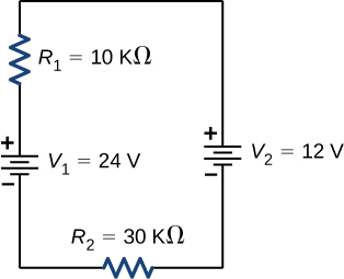
The figure shows positive terminal of voltage source V subscript 1 of 24 V connected in series to resistor R subscript 1 of 10 kΩ connected in series to positive terminal of voltage source V subscript 2 of 12 V connected in series to resistor R subscript 2 of 30 kΩ.

Answer

The circuit can be analyzed using Kirchhoff’s loop rule. The first voltage source supplies power: Pin= IV1= 7.20mW. The second voltage source consumes power: Pout= IV2+ I2R1+ I2R2= 7.2mW.

Check Your Understanding 10.7 §10.3 source ↗

When using Kirchhoff’s laws, you need to decide which loops to use and the direction of current flow through each loop. In analyzing the circuit in Example 10.7, the direction of current flow was chosen to be clockwise, from point a to point b. How would the results change if the direction of the current was chosen to be counterclockwise, from point b to point a?

Answer

The current calculated would be equal to I=−0.20A instead of I=0.20A. The sum of the power dissipated and the power consumed would still equal the power supplied.

Check Your Understanding 10.8 §10.4 source ↗

Digital meters are able to detect smaller currents than analog meters employing galvanometers. How does this explain their ability to measure voltage and current more accurately than analog meters?

Answer

Since digital meters require less current than analog meters, they alter the circuit less than analog meters. Their resistance as a voltmeter can be far greater than an analog meter, and their resistance as an ammeter can be far less than an analog meter. Consult Figure 10.36 and Figure 10.35 and their discussion in the text.
Figure 10.36 in the book ↗
To measure potential differences in this series circuit, the voltmeter (V) is placed in parallel with the voltage source or either of the resistors. Note that terminal voltage is measured between the positive terminal and the negative terminal of the battery or voltage source. It is not possible to connect a voltmeter directly across the emf without including the internal resistance r of the battery.
Figure 10.35 in the book ↗
(a) When an ammeter is used to measure the current through two resistors connected in series to a battery, a single ammeter is placed in series with the two resistors because the current is the same through the two resistors in series. (b) When two resistors are connected in parallel with a battery, three meters, or three separate ammeter readings, are necessary to measure the current from the battery and through each resistor. The ammeter is connected in series with the component in question.

10-1 §10.1 source ↗

What effect will the internal resistance of a rechargeable battery have on the energy being used to recharge the battery?

Answer

Some of the energy being used to recharge the battery will be dissipated as heat by the internal resistance.

10-3 §10.1 source ↗

Show that the power dissipated by the load resistor is maximum when the resistance of the load resistor is equal to the internal resistance of the battery.

Answer

P = I 2 R = ( ε r + R ) 2 R = ε 2 R ( r + R ) −2 , d P d R = ε 2 [ ( r + R ) −2 − 2 R ( r + R ) −3 ] = 0 , [ ( r + R ) − 2 R ( r + R ) 3 ] = 0 , r = R

10-5 §10.2 source ↗

The severity of a shock depends on the magnitude of the current through your body. Would you prefer to be in series or in parallel with a resistance, such as the heating element of a toaster, if you were shocked by it? Explain.

Answer

It would probably be better to be in series because the current will be less than if it were in parallel.

10-7 §10.2 source ↗

Some light bulbs have three power settings (not including zero), obtained from multiple filaments that are individually switched and wired in parallel. What is the minimum number of filaments needed for three power settings?

Answer

two filaments, a low resistance and a high resistance, connected in parallel

10-9 §10.3 source ↗

Consider the circuit shown below. Does the analysis of the circuit require Kirchhoff’s method, or can it be redrawn to simplify the circuit? If it is a circuit of series and parallel connections, what is the equivalent resistance?
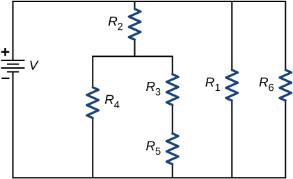
The figure shows a circuit with positive terminal of voltage source V connected to three parallel branches. The first branch has resistor R subscript 2 connected to parallel branches with R subscript 4 and R subscript 3 series with R subscript 5. The second branch has resistor R subscript 1 and third branch has resistor R subscript 6.

Answer

It can be redrawn.
Req= [1R6+1R1+1R2+(1R4+1R3+R5)−1]−1

10-11 §10.3 source ↗

What are the advantages and disadvantages of connecting batteries in series? In parallel?

Answer

In series the voltages add, but so do the internal resistances, because the internal resistances are in series. In parallel, the terminal voltage is the same, but the equivalent internal resistance is smaller than the smallest individual internal resistance and a higher current can be provided.

10-13 §10.4 source ↗

What would happen if you placed a voltmeter in series with a component to be tested?

Answer

The voltmeter would put a large resistance in series with the circuit, significantly changing the circuit. It would probably give a reading, but it would be meaningless.

10-15 §10.4 source ↗

Why should you not connect an ammeter directly across a voltage source as shown below?
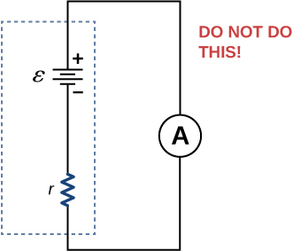
The figure shows positive terminal of a battery with emf ε and internal resistance r connected to ammeter.

Answer

The ammeter has a small resistance; therefore, a large current will be produced and could damage the meter and/or overheat the battery.

10-17 §10.5 source ↗

When making an ECG measurement, it is important to measure voltage variations over small time intervals. The time is limited by the RC constant of the circuit—it is not possible to measure time variations shorter than RC. How would you manipulate R and C in the circuit to allow the necessary measurements?

Answer

The time constant can be shortened by using a smaller resistor and/or a smaller capacitor. Care should be taken when reducing the resistance because the initial current will increase as the resistance decreases.

10-19 §10.6 source ↗

We are often advised to not flick electric switches with wet hands, dry your hand first. We are also advised to never throw water on an electric fire. Why?

Answer

Not only might water drip into the switch and cause a shock, but also the resistance of your body is lower when you are wet.

10-21 §10.1 source ↗

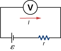
The label on a battery-powered radio recommends the use of a rechargeable nickel-cadmium cell (nicads), although it has a 1.25-V emf, whereas an alkaline cell has a 1.58-V emf. The radio has a 3.20Ω resistance. (a) Draw a circuit diagram of the radio and its battery. Now, calculate the power delivered to the radio (b) when using a nicad cells, each having an internal resistance of 0.0400Ω, and (c) when using an alkaline cell, having an internal resistance of 0.200Ω. (d) Does this difference seem significant, considering that the radio’s effective resistance is lowered when its volume is turned up?

Answer

a.

The figure shows a circuit with an emf source ε, resistor r and voltmeter V


b. 0.476W; c. 0.691 W; d. As RL is lowered, the power difference decreases; therefore, at higher volumes, there is no significant difference.

10-23 §10.1 source ↗

(a) What is the internal resistance of a voltage source if its terminal potential drops by 2.00 V when the current supplied increases by 5.00 A? (b) Can the emf of the voltage source be found with the information supplied?

Answer

a. 0.400Ω; b. No, there is only one independent equation, so only r can be found.

10-25 §10.1 source ↗

A 12.0-V emf automobile battery has a terminal voltage of 16.0 V when being charged by a current of 10.0 A. (a) What is the battery’s internal resistance? (b) What power is dissipated inside the battery? (c) At what rate (in °C/min) will its temperature increase if its mass is 20.0 kg and it has a specific heat of 0.300kcal/kg·°C, assuming no heat escapes?

Answer

a. 0.400Ω; b. 40.0 W; c. 0.0956°C/min

10-27 §10.2 source ↗

What are the largest and smallest resistances you can obtain by connecting a 36.0-Ω, a 50.0-Ω, and a 700-Ω resistor together?

Answer

largest, 786Ω, smallest, 20.32Ω

10-29 §10.2 source ↗

Your car’s 30.0-W headlight and 2.40-kW starter are ordinarily connected in parallel in a 12.0-V system. What power would one headlight and the starter consume if connected in series to a 12.0-V battery? (Neglect any other resistance in the circuit and any change in resistance in the two devices.)

Answer

29.6 W

10-31 §10.2 source ↗

Referring to the example combining series and parallel circuits and Figure 10.16, calculate I3 in the following two different ways: (a) from the known values of I and I2; (b) using Ohm’s law for R3. In both parts, explicitly show how you follow the steps in the Series and Parallel Resistors.
Figure 10.16 in the book ↗
These three resistors are connected to a voltage source so that R2 and R3 are in parallel with one another and that combination is in series with R1.

Answer

a. 0.74 A; b. 0.742 A

10-33 §10.2 source ↗

Refer to Figure 10.17 and the discussion of lights dimming when a heavy appliance comes on. (a) Given the voltage source is 120 V, the wire resistance is 0.800Ω, and the bulb is nominally 75.0 W, what power will the bulb dissipate if a total of 15.0 A passes through the wires when the motor comes on? Assume negligible change in bulb resistance. (b) What power is consumed by the motor?
Figure 10.17 in the book ↗
Why do lights dim when a large appliance is switched on? The answer is that the large current the appliance motor draws causes a significant IR drop in the wires and reduces the voltage across the light.

Answer

a. 60.8 W; b. 1.56 kW

10-35 §10.2 source ↗

Consider the circuit shown below. The terminal voltage of the battery is V=18.00V. (a) Find the equivalent resistance of the circuit. (b) Find the current through each resistor. (c) Find the potential drop across each resistor. (d) Find the power dissipated by each resistor. (e) Find the power supplied by the battery.
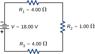
The figure shows negative terminal of a voltage source of 18 V connected to three resistors in series, R subscript 1 of 4 Ω, R subscript 2 of 1 Ω and R subscript 3 of 4 Ω.

Answer

a. Rs=9.00Ω; b.I1= I2= I3= 2.00A;
c. V1= 8.00V, V2= 2.00V, V3= 8.00V; d. P1= 16.00W, P2= 4.00W, P3= 16.00W; e. P=36.00W

10-37 §10.3 source ↗

Consider the circuits shown below. (a) What is the current through each resistor in part (a)? (b) What is the current through each resistor in part (b)? (c) What is the power dissipated or consumed by each circuit? (d) What is the power supplied to each circuit?
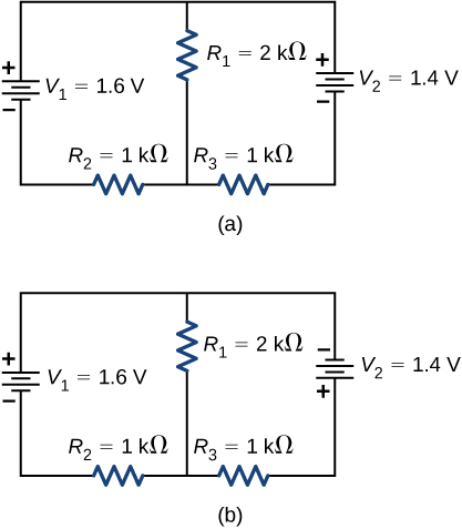
Part a shows positive terminal of voltage source V subscript 1 of 1.6 V connected to parallel branches, one with resistor R subscript 1 of 2 kΩ and second with positive terminal of voltage source V subscript 2 of 1.4 V and resistor R subscript 3 of 1 kΩ. The two branches are connected back to V subscript 1 through resistor R subscript 2 of 1 kΩ. Part b shows the same circuit as part a but the terminals of V subscript 2 are reversed.

Answer

a. I1= 0.6mA, I2= 0.4mA, I3= 0.2mA;
b. I1= 0.04mA, I2= 1.52mA, I3= −1.48mA; c. Pout= 0.92mW, Pout= 4.50mW;
d. Pin= 0.92mW, Pin= 4.50mW

10-39 §10.3 source ↗

Consider the circuit shown below. Find V1, V2, andR4.
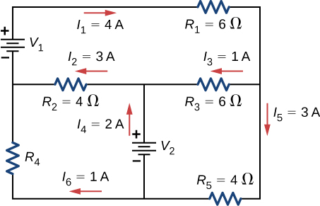
The figure shows a circuit with three horizontal branches. The first branch has resistor R subscript 1 of 6 Ω with right current I subscript 1 of 4 A. The second branch has resistor R subscript 2 of 4 Ω with left current I subscript 2 of 3 A and resistor R subscript 3 of 6 Ω with left current I subscript 3 of 1 A. The third branch has resistor R subscript 5 of 4 Ω with left current I subscript 5 of 3 A. The first and second horizontal branches are connected on the right directly and on the left with voltage source V subscript 1 with positive terminal connected to first branch. The second and third horizontal branches are connected on the right directly and on the left with resistor R subscript 4 with upward current I subscript 4 of 1 A. The second and third branches are also connected in the middle with a voltage source V subscript 2 with positive terminal connected to second branch.

Answer

V 1 = 42V, V 2 = 6V, R 4 = 6Ω

10-41 §10.3 source ↗

Consider the circuit shown below. (a) Find I1, I2, I3, I4, andI5. (b) Find the power supplied by the voltage sources. (c) Find the power dissipated by the resistors.
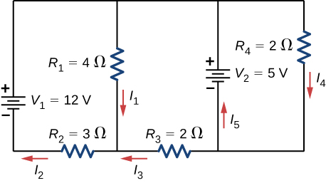
The circuit has four vertical branches. From left to right, first branch has voltage source V subscript 1 of 12 V with positive terminal upward. The second branch has resistor R subscript 1 of 4 Ω with downward current I subscript 1. The third branch has voltage source V subscript 2 of 5 V with positive terminal upward and upward current I subscript 5. The fourth branch has resistor R subscript 4 of 2 Ω with downward current I subscript 4. The first and second branch are connected at the bottom through resistor R subscript 2 of 3 Ω with left current I subscript 2 and second and third branch are connected at the bottom through resistor R subscript 3 of 2 Ω with left current I subscript 3.

Answer

a. I1= 1.5A, I2= 2A, I3= 0.5A, I4= 2.5A, I5= 2A; b. Pin= I2V1+ I5V5= 34W;
c. Pout= I12R1+ I22R2+ I32R3+ I42R4= 34W

10-43 §10.3 source ↗

Consider the circuit shown below. Write equations for the three currents in terms of R and V.
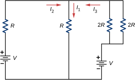
The circuit has four vertical branches. From left to right, first branch has voltage source V subscript 1 with positive terminal upward and resistor R. The second branch has resistor R with downward current I subscript 1. The third and fourth branches both have resistor 2 R and are connected to positive terminal of another voltage source V. The current between first and second branch is right I subscript 2 and between second and third branch is left I subscript 3.

Answer

I1= 23VR, I2= V3R, I3= V3R

10-45 §10.3 source ↗

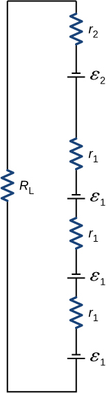
A child’s electronic toy is supplied by three 1.58-V alkaline cells having internal resistances of 0.0200Ω in series with a 1.53-V carbon-zinc dry cell having a 0.100-Ω internal resistance. The load resistance is 10.0Ω. (a) Draw a circuit diagram of the toy and its batteries. (b) What current flows? (c) How much power is supplied to the load? (d) What is the internal resistance of the dry cell if it goes bad, resulting in only 0.500 W being supplied to the load?

Answer

a.

The resistor R subscript L is connected in series with resistor r subscript 2, voltage source ε subscript 2, resistor r subscript 1, voltage source ε subscript 1, resistor r subscript 1, voltage source ε subscript 1, resistor r subscript 1and voltage source ε subscript 1. All voltage sources have upward negative terminals.

;
b. 0.617 A; c. 3.81 W; d. 18.0Ω

10-47 §10.3 source ↗

Apply the loop rule to Loop afedcba in the preceding problem.

Answer

I 1 r 1 − ε 1 + I 1 R 4 + ε 4 + I 2 r 4 + I 4 r 3 − ε 3 + I 2 R 3 + I 1 R 1 = 0

10-49 §10.5 source ↗

The timing device in an automobile’s intermittent wiper system is based on an RC time constant and utilizes a 0.500-μF capacitor and a variable resistor. Over what range must R be made to vary to achieve time constants from 2.00 to 15.0 s?

Answer

4.00 to 30.0 M Ω

10-51 §10.5 source ↗

The duration of a photographic flash is related to an RC time constant, which is 0.100μs for a certain camera. (a) If the resistance of the flash lamp is 0.0400Ω during discharge, what is the size of the capacitor supplying its energy? (b) What is the time constant for charging the capacitor, if the charging resistance is 800kΩ?

Answer

a. 2.50μF; b. 2.00 s

10-53 §10.5 source ↗

A 500-Ω resistor, an uncharged 1.50-μF capacitor, and a 6.16-V emf are connected in series. (a) What is the initial current? (b) What is the RC time constant? (c) What is the current after one time constant? (d) What is the voltage on the capacitor after one time constant?

Answer

a. 12.3 mA; b. 7.50×10⁻⁴s; c. 4.53 mA; d. 3.89 V

10-55 §10.5 source ↗

An ECG monitor must have an RC time constant less than 1.00×10²μs to be able to measure variations in voltage over small time intervals. (a) If the resistance of the circuit (due mostly to that of the patient’s chest) is 1.00kΩ, what is the maximum capacitance of the circuit? (b) Would it be difficult in practice to limit the capacitance to less than the value found in (a)?

Answer

a. 1.00×10⁻⁷F; b. No, in practice it would not be difficult to limit the capacitance to less than 100 nF, since typical capacitors range from fractions of a picofarad (pF) to milifarad (mF).

10-57 §10.5 source ↗

If you wish to take a picture of a bullet traveling at 500 m/s, then a very brief flash of light produced by an RC discharge through a flash tube can limit blurring. Assuming 1.00 mm of motion during one RC constant is acceptable, and given that the flash is driven by a 600-μF capacitor, what is the resistance in the flash tube?

Answer

3.33 × 10 −3 Ω

10-59 §10.6 source ↗

What voltage is involved in a 1.44-kW short circuit through a 0.100-Ω resistance?

Answer

12.0 V

10-61 §10.6 source ↗

While taking a bath, a person touches the metal case of a radio. The path through the person to the drainpipe and ground has a resistance of 4000Ω. What is the smallest voltage on the case of the radio that could cause ventricular fibrillation?

Answer

400 V

10-63 §10.6 source ↗

(a) During surgery, a current as small as 20.0μA applied directly to the heart may cause ventricular fibrillation. If the resistance of the exposed heart is 300Ω, what is the smallest voltage that poses this danger? (b) Does your answer imply that special electrical safety precautions are needed?

Answer

a. 6.00 mV; b. It would not be necessary to take extra precautions regarding the power coming from the wall. However, it is possible to generate voltages of approximately this value from static charge built up on gloves, for instance, so some precautions are necessary.

10-65 §10.6 source ↗

A heart defibrillator passes 10.0 A through a patient’s torso for 5.00 ms in an attempt to restore normal beating. (a) How much charge passed? (b) What voltage was applied if 500 J of energy was dissipated? (c) What was the path’s resistance? (d) Find the temperature increase caused in the 8.00 kg of affected tissue.

Answer

a. 5.00×10⁻²C; b. 10.0 kV; c. 1.00kΩ; d. 1.79×10⁻²°C

10-67 §10.AP source ↗

A circuit contains a D cell battery, a switch, a 20-Ω resistor, and four 20-mF capacitors connected in series. (a) What is the equivalent capacitance of the circuit? (b) What is the RC time constant? (c) How long before the current decreases to 50% of the initial value once the switch is closed?

Answer

a. Ceq=5.00mF; b. τ=0.1s; c. 0.069 s

10-69 §10.AP source ↗

Consider the circuit below. The battery has an emf of ε=30.00V and an internal resistance of r=1.00Ω. (a) Find the equivalent resistance of the circuit and the current out of the battery. (b) Find the current through each resistor. (c) Find the potential drop across each resistor. (d) Find the power dissipated by each resistor. (e) Find the total power supplied by the batteries.
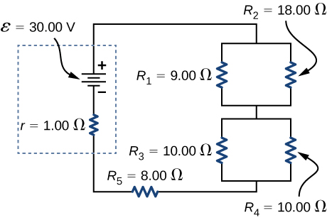
The figure shows positive terminal of voltage source of 30 V and internal resistance 1 Ω connected in series to two sets of parallel resistors. The first set has R subscript 1 of 9 Ω and R subscript 2 of 18 Ω. The second has R subscript 3 of 10 Ω and R subscript 4 of 10 Ω. The sets are connected in series to resistor R subscript 5 of 8 Ω.

Answer

a. Req=20.00Ω;
b. Ir= 1.50A, I1= 1.00A, I2= 0.50A, I3= 0.75A, I4= 0.75A, I5= 1.50A;
c. Vr= 1.50V, V1= 9.00V, V2= 9.00V, V3= 7.50V, V4= 7.50V, V5= 12.00V;
d. Pr= 2.25W, P1= 9.00W, P2= 4.50W, P3= 5.625W, P4= 5.625W, P5= 18.00W;
e. P=45.00W

10-71 §10.AP source ↗

A student makes a homemade resistor from a graphite pencil 5.00 cm long, where the graphite is 0.05 mm in diameter. The resistivity of the graphite is ρ= 1.38×10⁻⁵Ω/m. The homemade resistor is place in series with a switch, a 10.00-mF uncharged capacitor and a 0.50-V power source. (a) What is the RC time constant of the circuit? (b) What is the potential drop across the pencil 1.00 s after the switch is closed?

Answer

a. τ= (1.38×10⁻⁵Ωm(5.00×10⁻²m3.14(0.05×10⁻³²)2))10×10−3F= 3.52s; b. V= 0.014A(e−1.00s3.52s)351.59Ω= 0.376V

10-73 §10.AP source ↗

Three 300-Ω resistors are connect in series with an AAA battery with a rating of 3 AmpHours. (a) How long can the battery supply the resistors with power? (b) If the resistors are connected in parallel, how long can the battery last?

Answer

a. t= 3A·h1.5V900Ω= 1800h; b. t= 3A·h1.5V100Ω= 200h

10-75 §10.AP source ↗

Consider the circuit shown below. What is the energy stored in each capacitor after the switch has been closed for a very long time?
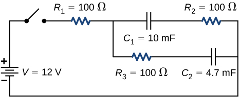
The positive terminal of voltage source V of 12 V is connected to an open switch. The other end of the open switch is connected to resistor R subscript 1 of 100 Ω which is connected to two parallel branches. The first branch has capacitor C subscript 1 of 10 mF and R subscript 2 of 100 Ω. The second branch has R subscript 3 of 100 Ω and C subscript 2 of 4.7 mF.

Answer

U 1 = C 1 V 1 2 = 0.72J, U 2 = C 2 V 2 2 = 0.338J

10-77 §10.AP source ↗

Consider the circuit shown below. The terminal voltages of the batteries are shown. (a) Find the equivalent resistance of the circuit and the current out of the battery. (b) Find the current through each resistor. (c) Find the potential drop across each resistor. (d) Find the power dissipated by each resistor. (e) Find the total power supplied by the batteries.
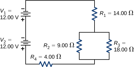
The figure shows two series voltage sources of 12 V each with upward negative terminals connected to four resistors. The sources are connected in series to resistor R subscript 1 of 14 Ω connected in series to two parallel resistors, R subscript 2 of 9 Ω and R subscript 3 of 18 Ω connected in series to resistor R subscript 4 of 4 Ω.

Answer

a. Req=24.00Ω; b. I1= 1.00A, I2= 0.67A, I3= 0.33A, I4= 1.00A;
c. V1= 14.00V, V2= 6.00V, V3= 6.00V, V4= 4.00V;
d. P1= 14.00W, P2= 4.04W, P3= 1.96W, P4= 4.00W; e. P=24.00W

10-79 §10.AP source ↗

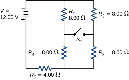
Consider the circuit shown below. (a)Determine the equivalent resistance and the current from the battery with switch S1 open. (b) Determine the equivalent resistance and the current from the battery with switch S1 closed.

The negative terminal of voltage source of 12 V is connected to two parallel branches, one with resistor R subscript 1 of 8 Ω in series with resistor R subscript 4 of 8 Ω and second with R subscript 2 of 8 Ω in series with R subscript 3 of 8 Ω. The branches are connected together to resistor R subscript 5 of 4 Ω. An open switch S connects the two branches in the middle.

Answer

a. Req= 12.00Ω, I= 1.00A; b. Req= 12.00Ω, I= 1.00A

10-81 §10.AP source ↗

Two resistors, one having a resistance of 900kΩ, are connected in series to produce a total resistance of 0.500MΩ. (a) What is the value of the second resistance? (b) What is unreasonable about this result? (c) Which assumptions are unreasonable or inconsistent?

Answer

a. −400kΩ; b. You cannot have negative resistance. c. The assumption that Req<R1 is unreasonable. Series resistance is always greater than any of the individual resistances.

10-83 §10.AP source ↗

Apply the loop rule to Loop akledcba in the preceding problem.

Answer

E 2 − I 2 r 2 − I 2 R 2 + I 1 R 5 + I 1 r 1 − E 1 + I 1 R 1 = 0

10-85 §10.AP source ↗

Consider the circuit shown below. (a) Find the current through each resistor. (b) Check the calculations by analyzing the power in the circuit.
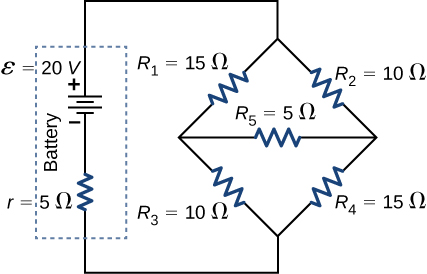
The positive terminal of voltage source of 20 V and internal resistance 5 Ω is connected to two parallel branches. The first branch has resistors R subscript 1 of 15 Ω and R subscript 3 of 10 Ω. The second branch has resistors R subscript 2 of 10 Ω and R subscript 4 of 15 Ω. The two branches are connected in the middle using resistor R subscript 5 of 5 Ω.

Answer

a. I= 1.17A, I1= 0.50A, I2= 0.67A, I3= 0.67A, I4= 0.50A, I5= 0.17A;
b. Poutput= 23.4W, Pinput= 23.4W

10-87 §10.AP source ↗

A 160-μF capacitor charged to 450 V is discharged through a 31.2-kΩ resistor. (a) Find the time constant. (b) Calculate the temperature increase of the resistor, given that its mass is 2.50 g and its specific heat is 1.67kJ/kg·°C, noting that most of the thermal energy is retained in the short time of the discharge. (c) Calculate the new resistance, assuming it is pure carbon. (d) Does this change in resistance seem significant?

Answer

a. 4.99 s; b. 3.87°C; c. 3.11×10⁴Ω; d. No, this change does not seem significant. It probably would not be noticed.

10-89 §10.CP source ↗

Consider the circuit shown below. Each battery has an emf of 1.50 V and an internal resistance of 1.00Ω. (a) What is the current through the external resistor, which has a resistance of 10.00 ohms? (b) What is the terminal voltage of each battery?
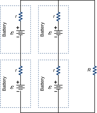
The circuit shows three parallel branches. The first and second branch both have two voltage sources ε with positive terminals upward and internal resistances r. The third branch has a resistor R.

Answer

a. 0.273 A; b. VT=1.36V

10-91 §10.CP source ↗

Analog meters use a galvanometer, which essentially consists of a coil of wire with a small resistance and a pointer with a scale attached. When current runs through the coil, the point turns; the amount the pointer turns is proportional to the amount of current running through the coil. Galvanometers can be used to make a voltmeter if a resistor is placed in series with the galvanometer. Consider a galvanometer that has a resistance of 25.00Ω and gives a full scale reading when a 50-μA current runs through it. The galvanometer is to be used to make an voltmeter that has a full scale reading of 10.00 V, as shown below. Recall that a voltmeter is connected in parallel with the component of interest, so the meter must have a high resistance or it will change the current running through the component. (a) What is the potential drop across the series resistor in the meter? (b) What is the resistance of the parallel resistor?
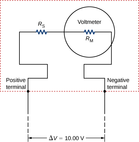
The figure shows a resistor R subscript S connected in series with a voltmeter with resistance R subscript M. The voltage difference across the ends is 10 V.

Answer

a. Vs= V− IMRM= 9.99875V; b. RS= VPIM= 199.975kΩ

10-93 §10.CP source ↗

Consider the circuit below. (a) What is the RC time constant of the circuit? (b) What is the initial current in the circuit once the switch is closed? (c) How much time passes between the instant the switch is closed and the time the current has reached half of the initial current?
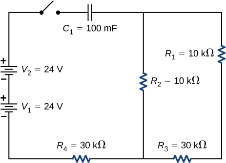
The circuit shows positive terminal of voltage source V subscript 1 of 24 V connected to negative terminal of voltage source of voltage source V subscript 2 of 24 V. The positive terminal of V subscript 2 is connected to an open switch. The other end of the switch is connected to capacitor C subscript 1 of 100 mF which is connected to two parallel branches, one with resistor R subscript 2 of 10 kΩ and other with R subscript 1 of 10 kΩ and R subscript 3 of 30 kΩ. The two branches are connected to source V subscript 1 through resistor R subscript 4 of 30 kΩ.

Answer

a. τ=3800s; b. 1.26 mA; c. t=2633.96s

10-95 §10.CP source ↗

Consider the infinitely long chain of resistors shown below. What is the resistance between terminals a and b?
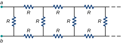
The circuit shows infinitely long circuit with vertical resistor R and its two ends connected to horizontal branches with resistors R connected to vertical resistor R connected to horizontal branches with resistors R and so on..

Answer

R eq = ( 3 – 1 ) R

10-97 §10.CP source ↗

A 120-V immersion heater consists of a coil of wire that is placed in a cup to boil the water. The heater can boil one cup of 20.00°C water in 180.00 seconds. You buy one to use in your dorm room, but you are worried that you will overload the circuit and trip the 15.00-A, 120-V circuit breaker, which supplies your dorm room. In your dorm room, you have four 100.00-W incandescent lamps and a 1500.00-W space heater. (a) What is the power rating of the immersion heater? (b) Will it trip the breaker when everything is turned on? (c) If it you replace the incandescent bulbs with 18.00-W LED, will the breaker trip when everything is turned on?

Answer

a. Pimheater= 1cup(0.000237m3cup)(1000kgm3)(4186Jkg °C)(100°C−20°C)180.00s≈ 441W;
b. I= 441W120V+ 4(100W120V)+ 1500W120V= 19.51A; Yes, the breaker will trip.
c. I= 441W120V+ 4(18W120V)+ 1500W120V= 16.78A; Yes, the breaker will trip.

10-99 §10.CP source ↗

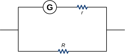
Find the resistance that must be placed in parallel with a 60.0-Ω galvanometer having a 1.00-mA sensitivity (the same as the one discussed in the text) to allow it to be used as an ammeter with a 25.0-A full-scale reading. Include a circuit diagram with your solution.

Answer


The figure shows a circuit with two parallel branches, one with galvanometer connected to resistors r and other with resistor R.

,
2.40×10⁻³Ω

Loading chapter 11…

Problems and answers are adapted from University Physics Volume 2 by Samuel J. Ling, Jeff Sanny and William Moebs, OpenStax, and are used under the CC BY-NC-SA 4.0 licence. Access for free at https://openstax.org/books/university-physics-volume-2/pages/1-introduction. Illustrations: Copyright Rice University, OpenStax, under CC BY-NC-SA 4.0 license. This adaptation is released under the same licence, is non-commercial, and is neither affiliated with nor endorsed by OpenStax or Rice University.