Every problem in the chapter beside the book’s answer, a chapter at a time as you scroll.

Chapter 15: Alternating-Current Circuits

45 problems · 6 figures

Check Your Understanding 15.1 §15.1 source ↗

If a European ac voltage source is considered, what is the time difference between the zero crossings on an ac voltage-versus-time graph?

Answer

10 ms

Check Your Understanding 15.2 §15.2 source ↗

Repeat Example 15.1 for an ac source of amplitude 20 V and frequency 100 Hz.

Answer

a. (20V)sin200πt,(0.20A)sin200πt; b. (20V)sin200πt,(0.13A)sin(200πt+π/2); c. (20V)sin200πt,(2.1A)sin(200πt−π/2)

Check Your Understanding 15.3 §15.3 source ↗

Find the voltages across the resistor, the capacitor, and the inductor in the circuit of Figure 15.11 using v(t)= V0sinωt as the output of the ac generator.
Figure 15.11 in the book ↗
(a) An RLC series circuit. (b) A comparison of the generator output voltage and the current. The value of the phase difference ϕ depends on the values of R, C, and L.

Answer

v R = ( V 0 R / Z ) sin ( ω t − ϕ ) ; v C = ( V 0 X C / Z ) sin ( ω t − ϕ + π / 2 ) = − ( V 0 X C / Z ) cos ( ω t − ϕ ) ; v L = ( V 0 X L / Z ) sin ( ω t − ϕ – π / 2 ) = ( V 0 X L / Z ) cos ( ω t − ϕ )

Check Your Understanding 15.4 §15.4 source ↗

An ac voltmeter attached across the terminals of a 45-Hz ac generator reads 7.07 V. Write an expression for the emf of the generator.

Answer

v(t)= (10.0V)sin90πt

Check Your Understanding 15.5 §15.4 source ↗

Show that the rms voltages across a resistor, a capacitor, and an inductor in an ac circuit where the rms current is Irms are given by IrmsR, IrmsXC, andIrmsXL, respectively. Determine these values for the components of the RLC circuit of Equation 15.12.

Answer

2.00 V; 10.01 V; 8.01 V

Check Your Understanding 15.6 §15.5 source ↗

In the circuit of Figure 15.11, L= 2.0×10⁻³H, C= 5.0×10⁻⁴F, and R=40Ω. (a) What is the resonant frequency? (b) What is the impedance of the circuit at resonance? (c) If the voltage amplitude is 10 V, what is i(t) at resonance? (d) The frequency of the AC generator is now changed to 200 Hz. Calculate the phase difference between the current and the emf of the generator.
Figure 15.11 in the book ↗
(a) An RLC series circuit. (b) A comparison of the generator output voltage and the current. The value of the phase difference ϕ depends on the values of R, C, and L.

Answer

a. 160 Hz; b. 40Ω; c. (0.25A)sin103t; d. 0.023 rad

Check Your Understanding 15.7 §15.5 source ↗

What happens to the resonant frequency of an RLC series circuit when the following quantities are increased by a factor of 4: (a) the capacitance, (b) the self-inductance, and (c) the resistance?

Answer

a. halved; b. halved; c. same

Check Your Understanding 15.8 §15.5 source ↗

The resonant angular frequency of an RLC series circuit is 4.0×10²rad/s. An ac source operating at this frequency transfers an average power of 2.0×10⁻²W to the circuit. The resistance of the circuit is 0.50Ω. Write an expression for the emf of the source.

Answer

v(t)= (0.14V)sin(4.0× 10 2 t)

Check Your Understanding 15.9 §15.6 source ↗

A transformer steps the line voltage down from 110 to 9.0 V so that a current of 0.50 A can be delivered to a doorbell. (a) What is the ratio of the number of turns in the primary and secondary windings? (b) What is the current in the primary winding? (c) What is the resistance seen by the 110-V source?

Answer

a. 12:1; b. 0.042 A; c. 2.6×10³Ω

15-1 §15.1 source ↗

What is the relationship between frequency and angular frequency?

Answer

Angular frequency is 2π times frequency.

15-3 §15.3 source ↗

In an RLC series circuit, can the voltage measured across the capacitor be greater than the voltage of the source? Answer the same question for the voltage across the inductor.

Answer

yes for both

15-5 §15.4 source ↗

Discuss the differences between average power and instantaneous power.

Answer

The instantaneous power is the power at a given instant. The average power is the power averaged over a cycle or number of cycles.

15-7 §15.4 source ↗

Can the instantaneous power output of an ac source ever be negative? Can the average power output be negative?

Answer

The instantaneous power can be negative, but the power output can’t be negative.

15-9 §15.6 source ↗

Why do transmission lines operate at very high voltages while household circuits operate at fairly small voltages?

Answer

There is less thermal loss if the transmission lines operate at low currents and high voltages.

15-11 §15.6 source ↗

Battery packs in some electronic devices are charged using an adapter connected to a wall socket. Speculate as to the purpose of the adapter.

Answer

The adapter has a step-down transformer to have a lower voltage and possibly higher current at which the device can operate.

15-13 §15.6 source ↗

Why are the primary and secondary coils of a transformer wrapped around the same closed loop of iron?

Answer

so each loop can experience the same changing magnetic flux

15-15 §15.2 source ↗

Calculate the reactance of a 5.0-μF capacitor at (a) 60 Hz, (b) 600 Hz, and (c) 6000 Hz.

Answer

a. 530Ω; b. 53Ω; c. 5.3Ω

15-17 §15.2 source ↗

Calculate the reactance of a 5.0-mH inductor at (a) 60 Hz, (b) 600 Hz, and (c) 6000 Hz.

Answer

a. 1.9Ω; b. 19Ω; c. 190Ω

15-19 §15.2 source ↗

At what frequency is the reactance of a 20-μF capacitor equal to that of a 10-mH inductor?

Answer

360 Hz

15-21 §15.2 source ↗

A 50-Ω resistor is connected across the emf v(t)= (160V)sin(120πt). Write an expression for the current through the resistor.

Answer

i(t)= (3.2A)sin(120πt)

15-23 §15.2 source ↗

A 100-mH inductor is connected across the emf of the preceding problem. (a) What is the reactance of the inductor? (b) Write an expression for the current through the inductor.

Answer

a. 38Ω; b. i(t)= (4.24A)sin(120πt−π/2)

15-25 §15.3 source ↗

A resistor and capacitor are connected in series across an ac generator. The emf of the generator is given by v(t)= V0cosωt, where V0=120V, ω= 120πrad/s, R=400Ω, and C=4.0μF. (a) What is the impedance of the circuit? (b) What is the amplitude of the current through the resistor? (c) Write an expression for the current through the resistor. (d) Write expressions representing the voltages across the resistor and across the capacitor.

Answer

a. 770Ω; b. 0.16 A; c. I= (0.16A)cos(120πt–0.33π); d. vR= 62cos(120πt–0.33π); vC= 103cos(120πt−0.83π)

15-27 §15.3 source ↗

In an RLC series circuit, the voltage amplitude and frequency of the source are 100 V and 500 Hz, respectively, an R=500Ω, L=0.20H, and C=2.0μF. (a) What is the impedance of the circuit? (b) What is the amplitude of the current from the source? (c) If the emf of the source is given by v(t)= (100V)sin1000πt, how does the current vary with time? (d) Repeat the calculations with C changed to 0.20μF.

Answer

a. 690Ω; b. 0.15 A; c. I= (0.15A)sin(1000πt−0.753); d. 1100Ω, 0.092 A, I= (0.092A)sin(1000πt+1.09)

15-29 §15.3 source ↗

For the circuit shown below, what are (a) the total impedance and (b) the phase angle between the current and the emf? (c) Write an expression for i(t).
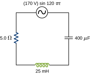
Figure shows a circuit with a voltage source 170 V, sine 120 pi t, a resistor of 5 ohm, a capacitor of 400 microfarad and an inductor of 25 milihenry all connected in series.

Answer

a. 5.7Ω; b. 29°; c. I​= (30.A)cos(120πt+0.51)

15-31 §15.4 source ↗

Calculate the rms currents for an ac source is given by v(t)= V0sinωt, where V0=100V and ω=200πrad/s when connected across (a) a 20-μF capacitor, (b) a 20-mH inductor, and (c) a 50-Ω resistor.

Answer

a. 0.89 A; b. 5.6A; c. 1.4 A

15-33 §15.4 source ↗

For an RLC series circuit, the voltage amplitude and frequency of the source are 100 V and 500 Hz, respectively; R=500Ω; and L=0.20H. Find the average power dissipated in the resistor for the following values for the capacitance: (a) C=2.0μF and (b) C=0.20μF.

Answer

a. 5.3 W; b. 2.1 W

15-35 §15.4 source ↗

An RLC series circuit has an impedance of 60Ω and a power factor of 0.50, with the voltage lagging the current. (a) Should a capacitor or an inductor be placed in series with the elements to raise the power factor of the circuit? (b) What is the value of the reactance across the inductor that will raise the power factor to unity?

Answer

a. inductor; b. XL=52Ω

15-37 §15.5 source ↗

The resonant frequency of an RLC series circuit is 2.0×10³Hz. If the self-inductance in the circuit is 5.0 mH, what is the capacitance in the circuit?

Answer

1.3 × 10 −6 F

15-39 §15.5 source ↗

For an RLC series circuit, R=100Ω, L=150mH, and C=0.25μF. (a) If an ac source of variable frequency is connected to the circuit, at what frequency is maximum power dissipated in the resistor? (b) What is the quality factor of the circuit?

Answer

a. 820 Hz; b. 7.8

15-41 §15.5 source ↗

(a) What is the resonant frequency of a resistor, capacitor, and inductor connected in series if R=100Ω, L=2.0H, and C=5.0μF? (b) If this combination is connected to a 100-V source operating at the resonant frequency, what is the power output of the source? (c) What is the Q of the circuit? (d) What is the bandwidth of the circuit?

Answer

a. 50 Hz; b. 50 W; c. 6.32; d. 50 rad/s

15-43 §15.5 source ↗

An ac generator is connected to a device whose internal circuits are not known. We only know current and voltage outside the device, as shown below. Based on the information given, what can you infer about the electrical nature of the device and its power usage?
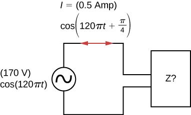
Figure shows an AC source connected to a box labeled Z. The source is 170V, cos 120 pi t. The current through the circuit is 0.5 Amp, cos parentheses 120 pi t plus pi by 4 parentheses.

Answer

The reactance of the capacitor is larger than the reactance of the inductor because the current leads the voltage. The power usage is 30 W.

15-45 §15.6 source ↗

A step-up transformer connected to a 110-V line is used to supply a hydrogen-gas discharge tube with 5.0 kV (rms). The tube dissipates 75 W of power. (a) What is the ratio of the number of turns in the secondary winding to the number of turns in the primary winding? (b) What are the rms currents in the primary and secondary windings? (c) What is the effective resistance seen by the 110-V source?

Answer

a. 45:1; b. 0.68 A, 0.015 A; c. 160Ω

15-47 §15.6 source ↗

A transformer is used to step down 110 V from a wall socket to 9.0 V for a radio. (a) If the primary winding has 500 turns, how many turns does the secondary winding have? (b) If the radio operates at a current of 500 mA, what is the current through the primary winding?

Answer

a. 41 turns; b. 40.9 mA

15-49 §15.AP source ↗

The emf of an ac source is given by v(t)= V0sinωt, where V0=100V and ω= 200πrad/s. Find an expression that represents the output current of the source if it is connected across (a) a 20-μF capacitor, (b) a 20-mH inductor, and (c) a 50-Ω resistor.

Answer

a. i(t)= (1.26A)sin(200πt+π/2); b. i(t)= (7.96A)sin(200πt−π/2); c. i(t)= (2A)sin(200πt)

15-51 §15.AP source ↗

A 20-mH inductor is connected across an AC source with a variable frequency and a constant-voltage amplitude of 9.0 V. (a) Determine the reactance of the circuit and the maximum current through the inductor when the frequency is set at 20 kHz. (b) Do the same calculations for a frequency of 60 Hz.

Answer

a. 2.5×10³Ω, 3.6×10⁻³A; b. 7.5Ω,1.2A

15-53 §15.AP source ↗

A 7.0-mH inductor is connected across a 60-Hz ac source whose voltage amplitude is 50 V. (a) What is the maximum current through the inductor? (b) What is the phase relationship between the current through and the potential difference across the inductor?

Answer

a. 19 A; b. inductor leads by 90°

15-55 §15.AP source ↗

What is the resistance R in the circuit shown below if the amplitude of the ac through the inductor is 4.24 A?
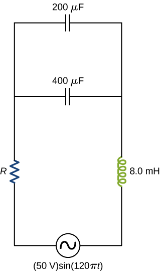
Figure shows a circuit with an AC source of 50 V, sine 120 pi t. This is connected to an inductor of 8 mH, a capacitor of 400 mu F and a resistor R. Another capacitor is connected in parallel with the first one. The value of this is 200 mu F.

Answer

11.7 Ω

15-57 §15.AP source ↗

In an RLC series circuit, R=200Ω, L=1.0H, C=50μF, V0=120V, and f=50Hz. What is the power output of the source?

Answer

14 W

15-59 §15.AP source ↗

Consider a power plant located 25 km outside a town delivering 50 MW of power to the town. The transmission lines are made of aluminum cables with a 7cm2 cross-sectional area. Find the loss of power in the transmission lines if it is transmitted at (a) 200 kV (rms) and (b) 120 V (rms).

Answer

a. 5.9×10⁴W; b. 1.64×10¹¹W

15-61 §15.CP source ↗

The 335-kV ac electricity from a power transmission line is fed into the primary winding of a transformer. The ratio of the number of turns in the secondary winding to the number in the primary winding is Ns/Np=1000. (a) What voltage is induced in the secondary winding? (b) What is unreasonable about this result? (c) Which assumption or premise is responsible?

Answer

a. 335 MV; b. the result is way too high, well beyond the breakdown voltage of air over reasonable distances; c. the input voltage is too high

15-63 §15.CP source ↗

A 20-Ω resistor, 50-μF capacitor, and 30-mH inductor are connected in series with an ac source of amplitude 10 V and frequency 125 Hz. (a) What is the impedance of the circuit? (b) What is the amplitude of the current in the circuit? (c) What is the phase constant of the current? Is it leading or lagging the source voltage? (d) Write voltage drops across the resistor, capacitor, and inductor and the source voltage as a function of time. (e) What is the power factor of the circuit? (f) How much energy is used by the resistor in 2.5 s?

Answer

a. 20Ω; b. 0.5 A; c. 5.4°, lagging;
d. VR=(9.96V)cos(250πt+5.4°),VC=(12.7V)cos(250πt+5.4°−90°),VL=(11.8V)cos(250πt+5.4°+90°),Vsource=(10.0​V)cos(250πt); e. 0.995; f. 6.25 J

15-65 §15.CP source ↗

Find the reactances of the following capacitors and inductors in ac circuits with the given frequencies in each case: (a) 2-mH inductor with a frequency 60-Hz of the ac circuit; (b) 2-mH inductor with a frequency 600-Hz of the ac circuit; (c) 20-mH inductor with a frequency 6-Hz of the ac circuit; (d) 20-mH inductor with a frequency 60-Hz of the ac circuit; (e) 2-mF capacitor with a frequency 60-Hz of the ac circuit; and (f) 2-mF capacitor with a frequency 600-Hz of the AC circuit.

Answer

a. 0.75Ω; b. 7.5Ω; c. 0.75Ω; d. 7.5Ω; e. 1.3Ω; f. 0.13Ω

15-67 §15.CP source ↗

Show that the SI unit for capacitive reactance is the ohm. Show that the SI unit for inductive reactance is also the ohm.

Answer

The units as written for inductive reactance Equation 15.8 are radsH. Radians can be ignored in unit analysis. The Henry can be defined as H=V·sA=Ω·s. Combining these together results in a unit of Ω for reactance.

15-69 §15.CP source ↗

An RLC series circuit consists of a 50-Ω resistor, a 200-μF capacitor, and a 120-mH inductor whose coil has a resistance of 20Ω. The source for the circuit has an rms emf of 240 V at a frequency of 60 Hz. Calculate the rms voltages across the (a) resistor, (b) capacitor, and (c) inductor.

Answer

a. 156 V; b. 42 V; c. 154 V

15-71 §15.CP source ↗

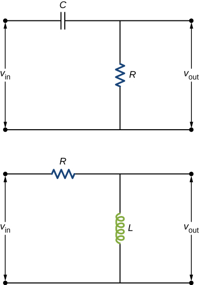
Shown below are two circuits that act as crude high-pass filters. The input voltage to the circuits is vin, and the output voltage is vout. (a) Show that for the capacitor circuit,

v out v in = 1 1 + 1 / ω 2 R 2 C 2 ,

and for the inductor circuit,

v out v in = ω L R 2 + ω 2 L 2 .

(b) Show that for high frequencies, vout≈vin, but for low frequencies, vout≈0.

Figure shows two circuits. The first shows a capacitor and resistor in series with a voltage source labeled V in. V out is measured across the resistor. The second circuit shows an inductor and resistor in series with a voltage source labeled V in. V out is measured across the inductor.

Answer

a. voutvin= 11+1/ω2R2C2 and voutvin= ωLR2+ω2L2; b. vout≈vin and vout≈0

Loading chapter 16…

Problems and answers are adapted from University Physics Volume 2 by Samuel J. Ling, Jeff Sanny and William Moebs, OpenStax, and are used under the CC BY-NC-SA 4.0 licence. Access for free at https://openstax.org/books/university-physics-volume-2/pages/1-introduction. Illustrations: Copyright Rice University, OpenStax, under CC BY-NC-SA 4.0 license. This adaptation is released under the same licence, is non-commercial, and is neither affiliated with nor endorsed by OpenStax or Rice University.