Every problem in the chapter beside the book’s answer, a chapter at a time as you scroll.

Chapter 8: Capacitance

50 problems · 6 figures

Check Your Understanding 8.1 §8.1 source ↗

The capacitance of a parallel-plate capacitor is 2.0 pF. If the area of each plate is 2.4cm2, what is the plate separation?

Answer

1.1 × 10 −3 m

Check Your Understanding 8.3 §8.1 source ↗

The radius of the outer sphere of a spherical capacitor is five times the radius of its inner shell. What are the dimensions of this capacitor if its capacitance is 5.00 pF?

Answer

3.59 cm, 17.98 cm

Check Your Understanding 8.4 §8.1 source ↗

When a cylindrical capacitor is given a charge of 0.500 nC, a potential difference of 20.0 V is measured between the cylinders. (a) What is the capacitance of this system? (b) If the cylinders are 1.0 m long, what is the ratio of their radii?

Answer

a. 25.0 pF; b. 9.2

Check Your Understanding 8.5 §8.2 source ↗

Determine the net capacitance C of each network of capacitors shown below. Assume that C1=1.0pF, C2=2.0pF, C3=4.0pF, and C4=5.0pF. Find the charge on each capacitor, assuming there is a potential difference of 12.0 V across each network.
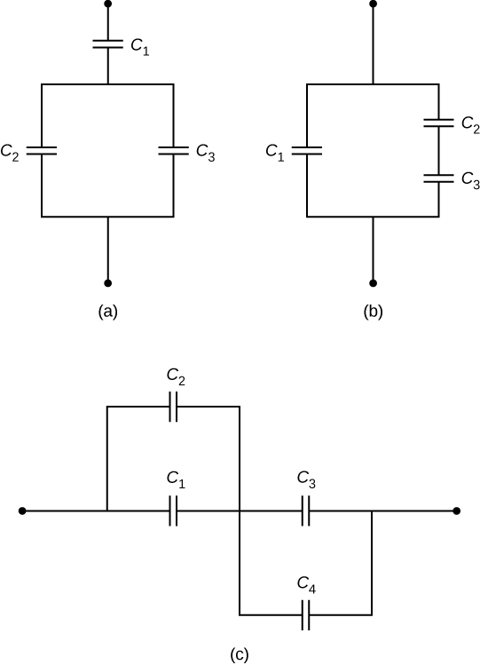
Figure a shows capacitors C2 and C3 in parallel with each other. They are in series with C1. Figure b shows capacitors C2 and C3 in series with each other. They are in parallel with C1. Figure c shows capacitors C1 and C2 in parallel with each other and capacitors C3 and C4 in parallel with each other. These combinations are connected in series.

Answer

a. C= 0.86pF,Q1= 10pC,Q2= 3.4pC,Q3= 6.8pC;
b. C= 2.3pF,Q1= 12pC,Q2= Q3= 16pC;
c. C= 2.3pF,Q1= 9.0pC,Q2= 18pC,Q3= 12pC,Q4= 15pC

Check Your Understanding 8.6 §8.3 source ↗

The potential difference across a 5.0-pF capacitor is 0.40 V. (a) What is the energy stored in this capacitor? (b) The potential difference is now increased to 1.20 V. By what factor is the stored energy increased?

Answer

a.4.0×10−13J; b. 9 times

Check Your Understanding 8.7 §8.4 source ↗

When a dielectric is inserted into an isolated and charged capacitor, the stored energy decreases to 33% of its original value. (a) What is the dielectric constant? (b) How does the capacitance change?

Answer

a. 3.0; b. C=3.0C0

Check Your Understanding 8.9 §8.5 source ↗

Repeat the calculations of Example 8.10 for the case in which the battery remains connected while the dielectric is placed in the capacitor.
Example 8.10 Inserting a Dielectric into an Isolated Capacitor in the book ↗

Answer

a. C0=20pF, C=42pF; b. Q0=0.8nC, Q=1.7nC; c. V0=V=40V; d. U0=16nJ, U=34nJ

8-1 §8.1 source ↗

Does the capacitance of a device depend on the applied voltage? Does the capacitance of a device depend on the charge residing on it?

Answer

no; no

8-3 §8.1 source ↗

The value of the capacitance is zero if the plates are not charged. True or false?

Answer

false

8-5 §8.1 source ↗

Does the capacitance of a spherical capacitor depend on which sphere is charged positively or negatively?

Answer

no

8-7 §8.2 source ↗

What is the maximum capacitance you can get by connecting three 1.0-μF capacitors? What is the minimum capacitance?

Answer

3.0μF, 0.33μF

8-9 §8.4 source ↗

Discuss what would happen if a conducting slab rather than a dielectric were inserted into the gap between the capacitor plates.

Answer

answers may vary

8-11 §8.5 source ↗

Distinguish between dielectric strength and dielectric constant.

Answer

Dielectric strength is a critical value of an electrical field above which an insulator starts to conduct; a dielectric constant is the ratio of the electrical field in vacuum to the net electrical field in a material.

8-13 §8.5 source ↗

Water has a high dielectric constant. Explain why it is then not used as a dielectric material in capacitors.

Answer

Water is a good solvent.

8-15 §8.5 source ↗

Explain why the dielectric constant of a substance containing permanent molecular electric dipoles decreases with increasing temperature.

Answer

When energy of thermal motion is large (high temperature), an electrical field must be large too in order to keep electric dipoles aligned with it.

8-17 §8.5 source ↗

Elaborate on the way in which the polar character of water molecules helps to explain water’s relatively large dielectric constant.

Answer

answers may vary

8-19 §8.1 source ↗

What charge is stored in a 180.0-μF capacitor when 120.0 V is applied to it?

Answer

21.6 mC

8-21 §8.1 source ↗

Calculate the voltage applied to a 2.00-μF capacitor when it holds 3.10μC of charge.

Answer

1.55 V

8-23 §8.1 source ↗

What capacitance is needed to store 3.00μC of charge at a voltage of 120 V?

Answer

25.0 nF

8-25 §8.1 source ↗

The plates of an empty parallel-plate capacitor of capacitance 5.0 pF are 2.0 mm apart. What is the area of each plate?

Answer

1.1 × 10 −3 m 2

8-27 §8.1 source ↗

A set of parallel plates has a capacitance of 5.0µF. How much charge must be added to the plates to increase the potential difference between them by 100 V?

Answer

500 µC

8-29 §8.1 source ↗

If the capacitance per unit length of a cylindrical capacitor is 20 pF/m, what is the ratio of the radii of the two cylinders?

Answer

1:16

8-31 §8.2 source ↗

A 4.00-pF is connected in series with an 8.00-pF capacitor and a 400-V potential difference is applied across the pair. (a) What is the charge on each capacitor? (b) What is the voltage across each capacitor?

Answer

a. 1.07 nC; b. 267 V, 133 V

8-33 §8.2 source ↗

Find the total capacitance of this combination of series and parallel capacitors shown below.
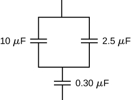
Figure shows capacitors of value 10 micro Farad and 2.5 micro Farad connected in parallel with each other. These are connected in series with a capacitor of value 0.3 micro Farad.

Answer

0.29 μ F

8-34 §8.2 source ↗

Suppose you need a capacitor bank with a total capacitance of 0.750 F but you have only 1.50-mF capacitors at your disposal. What is the smallest number of capacitors you could connect together to achieve your goal, and how would you connect them?

Answer

500 capacitors; connected in parallel

8-35 §8.2 source ↗

What total capacitances can you make by connecting a 5.00-μF and a 8.00-μF capacitor?

Answer

3.08μF (series) and 13.0μF (parallel)

8-37 §8.2 source ↗

Find the net capacitance of the combination of series and parallel capacitors shown below.
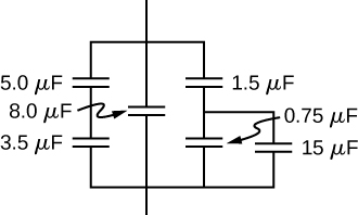
Figure shows a circuit with three branches connected in parallel with each other. Brach 1 has capacitors of value 5 micro Farad and 3.5 micro Farad connected in series with each other. Brach 2 has a capacitor of value 8 micro Farad. Brach 3 has three capacitors. Two of these, having values 0.75 micro Farad and 15 micro Farad are connected in parallel with each other. These are in series with the third capacitor of value 1.5 micro Farad.

Answer

11.4 μ F

8-39 §8.2 source ↗

A 2.0-μF capacitor and a 4.0-μF capacitor are connected in series across a 1.0-kV potential. The charged capacitors are then disconnected from the source and connected to each other with terminals of like sign together. Find the charge on each capacitor and the voltage across each capacitor.

Answer

0.89 mC; 1.78 mC; 444 V

8-41 §8.3 source ↗

A capacitor has a charge of 2.5μC when connected to a 6.0-V battery. How much energy is stored in this capacitor?

Answer

7.5 μ J

8-43 §8.3 source ↗

(a) What is the energy stored in the 10.0-μF capacitor of a heart defibrillator charged to 9.00×10³V ? (b) Find the amount of the stored charge.

Answer

a. 405 J; b. 90.0 mC

8-45 §8.3 source ↗

A 165-μF capacitor is used in conjunction with a dc motor. How much energy is stored in it when 119 V is applied?

Answer

1.17 J

8-47 §8.3 source ↗

An anxious physicist worries that the two metal shelves of a wood frame bookcase might obtain a high voltage if charged by static electricity, perhaps produced by friction. (a) What is the capacitance of the empty shelves if they have area 1.00×10²m2 and are 0.200 m apart? (b) What is the voltage between them if opposite charges of magnitude 2.00 nC are placed on them? (c) To show that this voltage poses a small hazard, calculate the energy stored. (d) The actual shelves have an area 100 times smaller than these hypothetical shelves with a connection to the same voltage. Are his fears justified?

Answer

a. 4.43×10⁻⁹F; b. 0.453 V; c. 4.53×10⁻¹⁰J; d. no

8-49 §8.3 source ↗

Suppose that the capacitance of a variable capacitor can be manually changed from 100 pF to 800 pF by turning a dial, connected to one set of plates by a shaft, from 0° to 180°. With the dial set at 180° (corresponding to C=800pF), the capacitor is connected to a 500-V source. After charging, the capacitor is disconnected from the source, and the dial is turned to 0°. If friction is negligible, how much work is required to turn the dial from 180° to 0° ?

Answer

0.7 mJ

8-51 §8.4 source ↗

An air-filled capacitor is made from two flat parallel plates 1.0 mm apart. The inside area of each plate is 8.0cm2. (a) What is the capacitance of this set of plates? (b) If the region between the plates is filled with a material whose dielectric constant is 6.0, what is the new capacitance?

Answer

a. 7.1 pF; b. 42 pF

8-53 §8.4 source ↗

A parallel-plate capacitor has charge of magnitude 9.00μC on each plate and capacitance 3.00μF when there is air between the plates. The plates are separated by 2.00 mm. With the charge on the plates kept constant, a dielectric with κ=5 is inserted between the plates, completely filling the volume between the plates. (a) What is the potential difference between the plates of the capacitor, before and after the dielectric has been inserted? (b) What is the electrical field at the point midway between the plates before and after the dielectric is inserted?

Answer

a. before 3.00 V; after 0.600 V; b. before 1500 V/m; after 300 V/m

8-55 §8.4 source ↗

A parallel-plate capacitor with only air between its plates is charged by connecting the capacitor to a battery. The capacitor is then disconnected from the battery, without any of the charge leaving the plates. (a) A voltmeter reads 45.0 V when placed across the capacitor. When a dielectric is inserted between the plates, completely filling the space, the voltmeter reads 11.5 V. What is the dielectric constant of the material? (b) What will the voltmeter read if the dielectric is now pulled away out so it fills only one-third of the space between the plates?

Answer

a. 3.91; b. 22.8 V

8-57 §8.5 source ↗

For a Teflon™-filled, parallel-plate capacitor, the area of the plate is 50.0cm2 and the spacing between the plates is 0.50 mm. If the capacitor is connected to a 200-V battery, find (a) the free charge on the capacitor plates, (b) the electrical field in the dielectric, and (c) the induced charge on the dielectric surfaces.

Answer

a. 37 nC; b. 0.4 MV/m; c. 19 nC

8-59 §8.5 source ↗

(a) What is the capacitance of a parallel-plate capacitor with plates of area 1.50m2 that are separated by 0.0200 mm of neoprene rubber? (b) What charge does it hold when 9.00 V is applied to it?

Answer

a. 4.4μF; b. 4.0×10⁻⁵C

8-61 §8.5 source ↗

The dielectric to be used in a parallel-plate capacitor has a dielectric constant of 3.60 and a dielectric strength of 1.60×10⁷V/m. The capacitor has to have a capacitance of 1.25 nF and must be able to withstand a maximum potential difference 5.5 kV. What is the minimum area the plates of the capacitor may have?

Answer

0.0135 m 2

8-63 §8.5 source ↗

A parallel-plate capacitor has square plates that are 8.00 cm on each side and 3.80 mm apart. The space between the plates is completely filled with two square slabs of dielectric, each 8.00 cm on a side and 1.90 mm thick. One slab is Pyrex glass and the other slab is polystyrene. If the potential difference between the plates is 86.0 V, find how much electrical energy can be stored in this capacitor.

Answer

0.185 μ J

8-65 §8.AP source ↗

An air-filled (empty) parallel-plate capacitor is made from two square plates that are 25 cm on each side and 1.0 mm apart. The capacitor is connected to a 50-V battery and fully charged. It is then disconnected from the battery and its plates are pulled apart to a separation of 2.00 mm. (a) What is the capacitance of this new capacitor? (b) What is the charge on each plate? (c) What is the electrical field between the plates?

Answer

a. 0.277 nF; b. 27.7 nC; c. 50 kV/m

8-67 §8.AP source ↗

Earth can be considered as a spherical capacitor with two plates, where the negative plate is the surface of Earth and the positive plate is the bottom of the ionosphere, which is located at an altitude of approximately 70 km. The potential difference between Earth’s surface and the ionosphere is about 350,000 V. (a) Calculate the capacitance of this system. (b) Find the total charge on this capacitor. (c) Find the energy stored in this system.

Answer

a. 0.065 F; b. 23,000 C; c. 4.0 GJ

8-69 §8.AP source ↗

Three capacitors having capacitances of 8.40, 8.40, and 4.20 μF, respectively, are connected in series across a 36.0-V potential difference. (a) What is the charge on the 4.20-μF capacitor? (b) The capacitors are disconnected from the potential difference without allowing them to discharge. They are then reconnected in parallel with each other with the positively charged plates connected together. What is the voltage across each capacitor in the parallel combination?

Answer

a. 75.6μC; b. 10.8 V

8-71 §8.AP source ↗

(a) How much energy is stored in the electrical fields in the capacitors (in total) shown below? (b) Is this energy equal to the work done by the 400-V source in charging the capacitors?
Figure 8.23 in the book ↗

Answer

a. 0.13 J; b. no, because of resistive heating in connecting wires that is always present, but the circuit schematic does not indicate resistors

8-73 §8.AP source ↗

(a) An 8.00-μF capacitor is connected in parallel to another capacitor, producing a total capacitance of 5.00μF. What is the capacitance of the second capacitor? (b) What is unreasonable about this result? (c) Which assumptions are unreasonable or inconsistent?

Answer

a. −3.00μF; b. You cannot have a negative C2 capacitance. c. The assumption that they were hooked up in parallel, rather than in series, is incorrect. A parallel connection always produces a greater capacitance, while here a smaller capacitance was assumed. This could only happen if the capacitors are connected in series.

8-75 §8.AP source ↗

(a) A certain parallel-plate capacitor has plates of area 4.00m2, separated by 0.0100 mm of nylon, and stores 0.170 C of charge. What is the applied voltage? (b) What is unreasonable about this result? (c) Which assumptions are responsible or inconsistent?

Answer

a. 14.2 kV; b. The voltage is unreasonably large, more than 100 times the breakdown voltage of nylon. c. The assumed charge is unreasonably large and cannot be stored in a capacitor of these dimensions.

8-77 §8.CP source ↗

A spherical capacitor is formed from two concentric spherical conducting spheres separated by vacuum. The inner sphere has radius 12.5 cm and the outer sphere has radius 14.8 cm. A potential difference of 120 V is applied to the capacitor. (a) What is the capacitance of the capacitor? (b) What is the magnitude of the electrical field at r=12.6cm, just outside the inner sphere? (c) What is the magnitude of the electrical field at r=14.7cm, just inside the outer sphere? (d) For a parallel-plate capacitor the electrical field is uniform in the region between the plates, except near the edges of the plates. Is this also true for a spherical capacitor?

Answer

a. 89.6 pF; b. 6.09 kV/m; c. 4.47 kV/m; d. no

8-79 §8.CP source ↗

Electronic flash units for cameras contain a capacitor for storing the energy used to produce the flash. In one such unit the flash lasts for 1/675 fraction of a second with an average light power output of 270 kW. (a) If the conversion of electrical energy to light is 95% efficient (because the rest of the energy goes to thermal energy), how much energy must be stored in the capacitor for one flash? (b) The capacitor has a potential difference between its plates of 125 V when the stored energy equals the value stored in part (a). What is the capacitance?

Answer

a. 421 J; b. 53.9 mF

8-81 §8.CP source ↗

A metal plate of thickness t is held in place between two capacitor plates by plastic pegs, as shown below. The effect of the pegs on the capacitance is negligible. The area of each capacitor plate and the area of the top and bottom surfaces of the inserted plate are all A. What is the capacitance of this system?
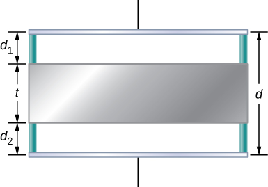
Figure shows two plates of a capacitor separated by a distance d. A metal plate of thickness t is shown in between the two plates. The distance of the metal from one capacitor plate is d1 and that from the other capacitor plate is d2.

Answer

C= ε0A/(d1+d2)

8-83 §8.CP source ↗

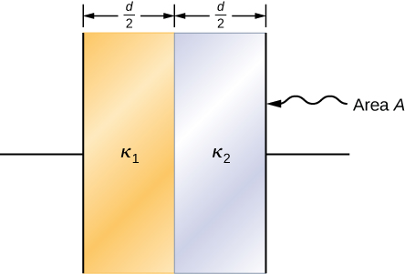
A parallel-plate capacitor is filled with two dielectrics, as shown below. Show that the capacitance is given by
C= 2 ε 0 A d κ 1 κ 2 κ 1 + κ 2 .

Figure shows two vertical plates of a capacitor. The left half of the area between them is filled with material labeled K1.The right half is filled with material labeled K2. Both K1 and K2 have thickness d by 2. The area of the capacitor plate is labeled A.

Answer

proof

Loading chapter 9…

Problems and answers are adapted from University Physics Volume 2 by Samuel J. Ling, Jeff Sanny and William Moebs, OpenStax, and are used under the CC BY-NC-SA 4.0 licence. Access for free at https://openstax.org/books/university-physics-volume-2/pages/1-introduction. Illustrations: Copyright Rice University, OpenStax, under CC BY-NC-SA 4.0 license. This adaptation is released under the same licence, is non-commercial, and is neither affiliated with nor endorsed by OpenStax or Rice University.