Every problem in the chapter beside the book’s answer, a chapter at a time as you scroll.

Chapter 14: Inductance

52 problems · 14 figures

Check Your Understanding 14.1 §14.1 source ↗

A current I(t)= (5.0A)sin((120πrad/s)t) flows through the solenoid of part (b) of Example 14.1. What is the maximum emf induced in the surrounding coil?

Answer

4.77 × 10 −2 V

Check Your Understanding 14.2 §14.2 source ↗

Current flows through the inductor in Figure 14.8 from B to A instead of from A to B as shown. Is the current increasing or decreasing in order to produce the emf given in diagram (a)? In diagram (b)?
Figure 14.8 in the book ↗
The induced emf across an inductor always acts to oppose the change in the current. This can be visualized as an imaginary battery causing current to flow to oppose the change in (a) and reinforce the change in (b).

Answer

a. decreasing; b. increasing; Since the current flows in the opposite direction of the diagram, in order to get a positive emf on the left-hand side of diagram (a), we need to decrease the current to the left, which creates a reinforced emf where the positive end is on the left-hand side. To get a positive emf on the right-hand side of diagram (b), we need to increase the current to the left, which creates a reinforced emf where the positive end is on the right-hand side.

Check Your Understanding 14.3 §14.2 source ↗

A changing current induces an emf of 10 V across a 0.25-H inductor. What is the rate at which the current is changing?

Answer

40 A/s

Check Your Understanding 14.4 §14.2 source ↗

(a) Calculate the self-inductance of a solenoid that is tightly wound with wire of diameter 0.10 cm, has a cross-sectional area of 0.90cm2, and is 40 cm long. (b) If the current through the solenoid decreases uniformly from 10 to 0 A in 0.10 s, what is the emf induced between the ends of the solenoid?

Answer

a. 4.5×10⁻⁵H; b. 4.5×10⁻³V

Check Your Understanding 14.5 §14.2 source ↗

(a) What is the magnetic flux through one turn of a solenoid of self-inductance 8.0×10⁻⁵H when a current of 3.0 A flows through it? Assume that the solenoid has 1000 turns and is wound from wire of diameter 1.0 mm. (b) What is the cross-sectional area of the solenoid?

Answer

a. 2.4×10⁻⁷Wb; b. 6.4×10⁻⁵m2

Check Your Understanding 14.6 §14.3 source ↗

How much energy is stored in the inductor of Example 14.2 after the current reaches its maximum value?
Example 14.2 Self-Inductance of a Coil in the book ↗

Answer

0.50 J

Check Your Understanding 14.8 §14.4 source ↗

(a) If the current in the circuit of in Figure 14.12(b) increases to 90% of its final value after 5.0 s, what is the inductive time constant? (b) If R=20Ω, what is the value of the self-inductance? (c) If the 20-Ω resistor is replaced with a 100-Ω resister, what is the time taken for the current to reach 90% of its final value?
Figure 14.12 in the book ↗
(a) An RL circuit with switches S1 and S2. (b) The equivalent circuit with S1 closed and S2 open. (c) The equivalent circuit after S1 is opened and S2 is closed.

Answer

a. 2.2 s; b. 43 H; c. 1.0 s

Check Your Understanding 14.10 §14.5 source ↗

The angular frequency of the oscillations in an LC circuit is 2.0×10³ rad/s. (a) If L=0.10H, what is C? (b) Suppose that at t=0, all the energy is stored in the inductor. What is the value of ϕ? (c) A second identical capacitor is connected in parallel with the original capacitor. What is the angular frequency of this circuit?

Answer

a. 2.5μF; b. π/2rad or3π/2rad; c. 1.4×10³rad/s

Check Your Understanding 14.11 §14.6 source ↗

In an RLC circuit, L= 5.0mH, C= 6.0μF, andR= 200Ω. (a) Is the circuit underdamped, critically damped, or overdamped? (b) If the circuit starts oscillating with a charge of 3.0×10⁻³C on the capacitor, how much energy has been dissipated in the resistor by the time the oscillations cease?

Answer

a. overdamped; b. 0.75 J

14-1 §14.1 source ↗

Show that NΦm/I and ε/(dI/dt), which are both expressions for self-inductance, have the same units.

Answer

Wb A = T · m 2 A = V · s A = V A/s

14-3 §14.1 source ↗

The ignition circuit of an automobile is powered by a 12-V battery. How are we able to generate large voltages with this power source?

Answer

The induced current from the 12-V battery goes through an inductor, generating a large voltage.

14-5 §14.2 source ↗

Does self-inductance depend on the value of the magnetic flux? Does it depend on the current through the wire? Correlate your answers with the equation NΦm=LI.

Answer

Self-inductance is proportional to the magnetic flux and inversely proportional to the current. However, since the magnetic flux depends on the current I, these effects cancel out. This means that the self-inductance does not depend on the current. If the emf is induced across an element, it does depend on how the current changes with time.

14-7 §14.2 source ↗

Discuss how you might determine the self-inductance per unit length of a long, straight wire.

Answer

Consider the ends of a wire a part of an RL circuit and determine the self-inductance from this circuit.

14-9 §14.2 source ↗

How does the self-inductance per unit length near the center of a solenoid (away from the ends) compare with its value near the end of the solenoid?

Answer

The magnetic field will flare out at the end of the solenoid so there is less flux through the last turn than through the middle of the solenoid.

14-11 §14.4 source ↗

Use Lenz’s law to explain why the initial current in the RL circuit of Figure 14.12(b) is zero.
Figure 14.12 in the book ↗
(a) An RL circuit with switches S1 and S2. (b) The equivalent circuit with S1 closed and S2 open. (c) The equivalent circuit after S1 is opened and S2 is closed.

Answer

As current flows through the inductor, there is a back current by Lenz’s law that is created to keep the net current at zero amps, the initial current.

14-13 §14.4 source ↗

Does the time required for the current in an RL circuit to reach any fraction of its steady-state value depend on the emf of the battery?

Answer

no

14-15 §14.4 source ↗

At what time is the voltage across the inductor of the RL circuit of Figure 14.12(b) a maximum?
Figure 14.12 in the book ↗
(a) An RL circuit with switches S1 and S2. (b) The equivalent circuit with S1 closed and S2 open. (c) The equivalent circuit after S1 is opened and S2 is closed.

Answer

At t=0, or when the switch is first thrown.

14-17 §14.4 source ↗

If the emf of the battery of Figure 14.12(b) is reduced by a factor of 2, by how much does the steady-state energy stored in the magnetic field of the inductor change?
Figure 14.12 in the book ↗
(a) An RL circuit with switches S1 and S2. (b) The equivalent circuit with S1 closed and S2 open. (c) The equivalent circuit after S1 is opened and S2 is closed.

Answer

1/4

14-19 §14.4 source ↗

Describe how the currents through R1andR2 shown below vary with time after switch S is closed.
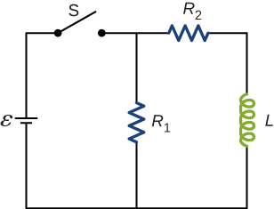
Figure shows a circuit with resistor R1 connected in series with battery epsilon, through open switch S. R1 is parallel to resistor R2 and inductor L.

Answer

Initially, IR1=εR1 and IR2=0, and after a long time has passed, IR1=εR1 and IR2=εR2.

14-21 §14.5 source ↗

Do Kirchhoff’s rules apply to circuits that contain inductors and capacitors?

Answer

yes

14-23 §14.5 source ↗

In an LC circuit, what determines the frequency and the amplitude of the energy oscillations in either the inductor or capacitor?

Answer

The amplitude of energy oscillations depend on the initial energy of the system. The frequency in a LC circuit depends on the values of inductance and capacitance.

14-25 §14.6 source ↗

Describe what effect the resistance of the connecting wires has on an oscillating LC circuit.

Answer

This creates an RLC circuit that dissipates energy, causing oscillations to decrease in amplitude slowly or quickly depending on the value of resistance.

14-27 §14.6 source ↗

A radio receiver uses an RLC circuit to pick out particular frequencies to listen to in your house or car without hearing other unwanted frequencies. How would someone design such a circuit?

Answer

You would have to pick out a resistance that is small enough so that only one station at a time is picked up, but big enough so that the tuner doesn’t have to be set at exactly the correct frequency. The inductance or capacitance would have to be varied to tune into the station however practically speaking, variable capacitors are a lot easier to build in a circuit.

14-29 §14.1 source ↗

An emf of 9.7×10⁻³V is induced in a coil while the current in a nearby coil is decreasing at a rate of 2.7 A/s. What is the mutual inductance of the two coils?

Answer

M = 3.6 × 10 −3 H

14-31 §14.1 source ↗

A coil of 40 turns is wrapped around a long solenoid of cross-sectional area 7.5×10⁻³m2. The solenoid is 0.50 m long and has 500 turns. (a) What is the mutual inductance of this system? (b) The outer coil is replaced by a coil of 40 turns whose radius is three times that of the solenoid. What is the mutual inductance of this configuration?

Answer

a. 3.8×10⁻⁴H; b. 3.8×10⁻⁴H

14-33 §14.1 source ↗

A toroidal coil has a mean radius of 16 cm and a cross-sectional area of 0.25cm2; it is wound uniformly with 1000 turns. A second toroidal coil of 750 turns is wound uniformly over the first coil. Ignoring the variation of the magnetic field within a toroid, determine the mutual inductance of the two coils.

Answer

M 21 = 2.3× 10 −5 H

14-35 §14.2 source ↗

An emf of 0.40 V is induced across a coil when the current through it changes uniformly from 0.10 to 0.60 A in 0.30 s. What is the self-inductance of the coil?

Answer

0.24 H

14-37 §14.2 source ↗

What is the rate at which the current though a 0.30-H coil is changing if an emf of 0.12 V is induced across the coil?

Answer

0.4 A/s

14-39 §14.2 source ↗

A coil with a self-inductance of 2.0 H carries a current that varies with time according to I(t)= (2.0A)sin120πt. Find an expression for the emf induced in the coil.

Answer

ε= 480πsin(120πt−π/2)V

14-41 §14.2 source ↗

A coil with a self-inductance of 3.0 H carries a current that decreases at a uniform rate dI/dt= −0.050A/s. What is the emf induced in the coil? Describe the polarity of the induced emf.

Answer

0.15 V. This is the same polarity as the emf driving the current.

14-43 §14.2 source ↗

A long, cylindrical solenoid with 100 turns per centimeter has a radius of 1.5 cm. (a) Neglecting end effects, what is the self-inductance per unit length of the solenoid? (b) If the current through the solenoid changes at the rate 5.0 A/s, what is the emf induced per unit length?

Answer

a. 0.089 H/m; b. 0.44 V/m

14-45 §14.2 source ↗

What is the self-inductance per meter of a coaxial cable whose inner radius is 0.50 mm and whose outer radius is 4.00 mm?

Answer

L l = 4.16× 10 −7 H/m

14-47 §14.3 source ↗

Suppose that a rectangular toroid has 2000 windings and a self-inductance of 0.040 H. If h=0.10m, what is the current flowing through a rectangular toroid when the energy in its magnetic field is 2.0×10⁻⁶J?

Answer

0.01 A

14-49 §14.3 source ↗

A 10-H inductor carries a current of 20 A. How much ice at 0°C could be melted by the energy stored in the magnetic field of the inductor? (Hint: Use the value Lf=334J/g for ice.)

Answer

6.0 g

14-51 §14.3 source ↗

A current of 1.2 A is flowing in a coaxial cable whose outer radius is five times its inner radius. What is the magnetic field energy stored in a 3.0-m length of the cable?

Answer

U m = 7.0× 10 −7 J

14-53 §14.4 source ↗

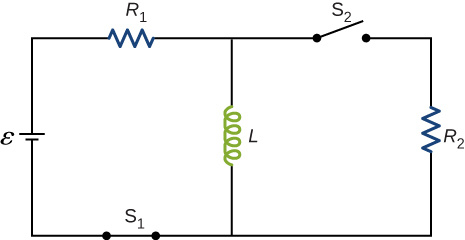
For the circuit shown below, ε=20V, L=4.0mH, and R=5.0Ω. After steady state is reached with S1 closed and S2 open, S2 is closed and immediately thereafter (att=0) S1 is opened. Determine (a) the current through L at t=0, (b) the current through L at t=4.0×10⁻⁴s, and (c) the voltages across L and R2 at t=4.0×10⁻⁴s. R1=R2=R.

Figure shows a circuit with R and L connected in series with battery epsilon through closed switch S. L is connected in parallel with another resistor R through open switch S2.

Answer

a. 4.0 A; b. 2.4 A; c. on R: V=12V; on L: V=12V

14-55 §14.4 source ↗

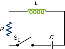
How long after switch S1 is thrown does it take the current in the circuit shown to reach half its maximum value? Express your answer in terms of the time constant of the circuit.
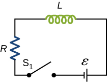
Figure shows a circuit with R and L in series with a battery, epsilon and a switch S1 which is open.

Answer

0.69 τ

14-57 §14.4 source ↗

The current in the RL circuit shown below reaches half its maximum value in 1.75 ms after the switch S1 is thrown. Determine (a) the time constant of the circuit and (b) the resistance of the circuit if L=250mH.

Figure shows a circuit with R and L in series with a battery, epsilon and a switch S1 which is open.

Answer

a. 2.52 ms; b. 99.2Ω

14-59 §14.4 source ↗

For the circuit shown below, ε=50V, R1=10Ω,, R2= R3= 19.4 Ω,, and L=2.0mH. Find the values of I1andI2 (a) immediately after switch S is closed, (b) a long time after S is closed, (c) immediately after S is reopened, and (d) a long time after S is reopened.
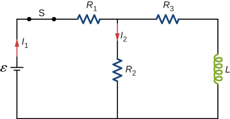
Figure shows a circuit with R1 and R2 connected in series with a battery, epsilon and a closed switch S. R2 is connected in parallel with L and R3. The currents through R1 and R2 are I1 and I2 respectively.

Answer

a. I1=I2=1.7A; b. I1= 2.54A, I2= 1.27A; c. I1= 0, I2= 1.27A; d. I1=I2=0

14-61 §14.4 source ↗

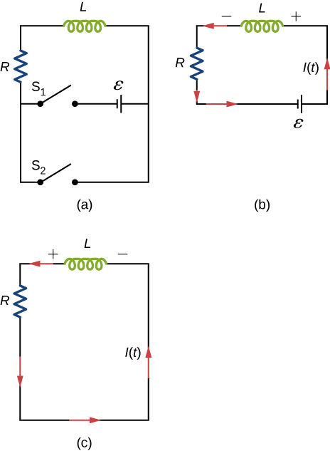
Show that for the circuit shown below, the initial energy stored in the inductor, LI2(0)/2, is equal to the total energy eventually dissipated in the resistor, ∫0∞I2(t)Rdt.

Figure a shows a resistor R and an inductor L connected in series with two switches which are parallel to each other. Both switches are currently open. Closing switch S1 would connect R and L in series with a battery, whose positive terminal is towards L. Closing switch S2 would form a closed loop of R and L, without the battery. Figure b shows a closed circuit with R, L and the battery in series. The side of L towards the battery, is at positive potential. Current flows from the positive end of L, through it, to the negative end. Figure c shows R and L connected in series. The potential across L is reversed, but the current flows in the same direction as in figure b.

Answer

proof

14-63 §14.5 source ↗

The self-inductance and capacitance of an LC circuit are 0.20 mH and 5.0 pF. What is the angular frequency at which the circuit oscillates?

Answer

ω= 3.2× 10 7 rad/s

14-65 §14.5 source ↗

In an oscillating LC circuit, the maximum charge on the capacitor is 2.0×10⁻⁶C and the maximum current through the inductor is 8.0 mA. (a) What is the period of the oscillations? (b) How much time elapses between an instant when the capacitor is uncharged and the next instant when it is fully charged?

Answer

a. 1.6×10⁻³s; b. 3.9×10⁻⁴s

14-67 §14.5 source ↗

In an oscillating LC circuit, the maximum charge on the capacitor is qm. Determine the charge on the capacitor and the current through the inductor when energy is shared equally between the electric and magnetic fields. Express your answer in terms of qm, L, and C.

Answer

q= q m 2 , I= q m 2 L C

14-69 §14.5 source ↗

An LC circuit in an AM tuner (in a car stereo) uses a coil with an inductance of 2.5 mH and a variable capacitor. If the natural frequency of the circuit is to be adjustable over the range 540 to 1600 kHz (the AM broadcast band), what range of capacitance is required?

Answer

C = 1 4 π 2 f 2 L f 1 = 540 Hz; C 1 = 3.5 × 10 −11 F f 2 = 1600 Hz; C 2 = 4.0 × 10 −12 F

14-71 §14.6 source ↗

In an oscillating RLC circuit with L= 10mH, C= 1.5µF, andR= 2.0Ω, how much time elapses before the amplitude of the oscillations drops to half its initial value?

Answer

6.9 ms

14-73 §14.AP source ↗

Show that the self-inductance per unit length of an infinite, straight, thin wire is infinite.

Answer

Let a equal the radius of the long, thin wire, r the location where the magnetic field is measured, and R the upper limit of the problem where we will take R as it approaches infinity.
proof Outside,B=μ0I2πrInside,B=μ0Ir2πa2 U=μ0I2l4π(14+lnRa) So,2UI2=μ0l2π(14+lnRa)andL=∞

14-75 §14.AP source ↗

A small, rectangular single loop of wire with dimensions l, and a is placed, as shown below, in the plane of a much larger, rectangular single loop of wire. The two short sides of the larger loop are so far from the smaller loop that their magnetic fields over the smaller fields over the smaller loop can be ignored. What is the mutual inductance of the two loops?
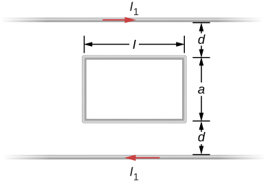
The figure shows a rectangular loop of wire. The length of the rectangle is l and width is a. On both sides of the rectangle are wires parallel to its length. They are a distance d away from the rectangle. Current I1 flows through both in opposites directions.

Answer

M= μ 0 l π ln d + a d

14-77 §14.AP source ↗

A solenoid with 4x10⁷ turns/m has an iron core placed in it whose magnetic susceptibility is 4.0×10³. (a) If a current of 2.0 A flows through the solenoid, what is the magnetic field in the iron core? (b) What is the effective surface current formed by the aligned atomic current loops in the iron core? (c) What is the self-inductance of the filled solenoid?

Answer

a. 100 T; b. 2 A; c. 0.50 H

14-79 §14.AP source ↗

The switch S of the circuit shown below is closed at t=0. Determine (a) the initial current through the battery and (b) the steady-state current through the battery.
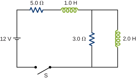
A 12 volt battery is connected in series with a 5 ohm resistor, a 1 Henry inductor, a 3 ohm resistor and an open switch S. Parallel to the 3 ohm resistor is a 2 Henry inductor.

Answer

a. 0 A; b. 2.4 A

14-81 §14.AP source ↗

A 25.0-H inductor has 100 A of current turned off in 1.00 ms. (a) What voltage is induced to oppose this? (b) What is unreasonable about this result? (c) Which assumption or premise is responsible?

Answer

a. 2.50×10⁶V; (b) The voltage is so extremely high that arcing would occur and the current would not be reduced so rapidly. (c) It is not reasonable to shut off such a large current in such a large inductor in such an extremely short time.

14-83 §14.CP source ↗

In a damped oscillating circuit the energy is dissipated in the resistor. The Q-factor is a measure of the persistence of the oscillator against the dissipative loss. (a) Prove that for a lightly damped circuit the energy, U, in the circuit decreases according to the following equation.

dUdt=−2βU, where β=R2L.

(b) Using the definition of the Q-factor as energy divided by the loss over the next cycle, prove that Q-factor of a lightly damped oscillator as defined in this problem is

Q≡ U begin Δ U one cycle = 1 2 π R L C .

(Hint: For (b), to obtain Q, divide E at the beginning of one cycle by the change ΔE over the next cycle.)

Answer

proof

14-85 §14.CP source ↗

A square loop of side 2 cm is placed 1 cm from a long wire carrying a current that varies with time at a constant rate of 3 A/s as shown below. (a) Use Ampère’s law and find the magnetic field. (b) Determine the magnetic flux through the loop. (c) If the loop has a resistance of 3Ω, how much induced current flows in the loop?
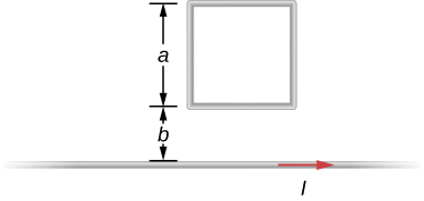
A 12 volt battery is connected to a 6 ohm resistor and a switch S, which is open at time t=0. Connected in parallel with the 6 ohm resistor are another 6 ohm resistor and a 24 Henry inductor.

Answer

a. dBdt= 6×10⁻⁶T/s; b. Φ= μ0aI2πln(a+bb); c. 4.4 nA

Loading chapter 15…

Problems and answers are adapted from University Physics Volume 2 by Samuel J. Ling, Jeff Sanny and William Moebs, OpenStax, and are used under the CC BY-NC-SA 4.0 licence. Access for free at https://openstax.org/books/university-physics-volume-2/pages/1-introduction. Illustrations: Copyright Rice University, OpenStax, under CC BY-NC-SA 4.0 license. This adaptation is released under the same licence, is non-commercial, and is neither affiliated with nor endorsed by OpenStax or Rice University.