Every problem in the chapter beside the book’s answer, a chapter at a time as you scroll.

Chapter 13: Electromagnetic Induction

54 problems · 24 figures

Check Your Understanding 13.1 §13.1 source ↗

A closely wound coil has a radius of 4.0 cm, 50 turns, and a total resistance of 40Ω. At what rate must a magnetic field perpendicular to the face of the coil change in order to produce heating in the coil at a rate of 2.0 mW?

Answer

1.1 T/s

Check Your Understanding 13.2 §13.2 source ↗

Find the direction of the induced current in the wire loop shown below as the magnet enters, passes through, and leaves the loop.
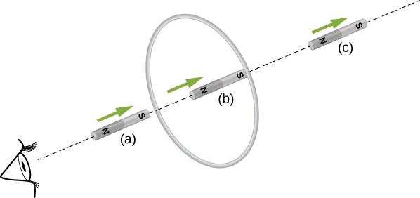
Figure shows a magnet that is moving into and through the loop with the South pole facing the loop. Position (a) corresponds to magnet approaching the loop; position (b) corresponds to the magnet directly into the loop. Position (c) corresponds to the magnet moving away from the loop.

Answer

To the observer shown, the current flows clockwise as the magnet approaches, decreases to zero when the magnet is centered in the plane of the coil, and then flows counterclockwise as the magnet leaves the coil.

Check Your Understanding 13.4 §13.3 source ↗

Shown below is a rod of length l that is rotated counterclockwise around the axis through O by the torque due to mg→. Assuming that the rod is in a uniform magnetic field B→, what is the emf induced between the ends of the rod when its angular velocity is ω? Which end of the rod is at a higher potential?
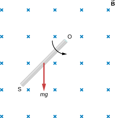
Figure shows a rod of length l that is located in the uniform magnetic field. The rod is rotated counterclockwise around the axis through O by the torque due to mg.

Answer

ε=Bl2ω/2, with O at a higher potential than S

Check Your Understanding 13.5 §13.3 source ↗

A rod of length 10 cm moves at a speed of 10 m/s perpendicularly through a 1.5-T magnetic field. What is the potential difference between the ends of the rod?

Answer

1.5 V

Check Your Understanding 13.6 §13.4 source ↗

Suppose that the coil of Example 13.2 is a square rather than circular. Can Equation 13.12 be used to calculate (a) the induced emf and (b) the induced electric field?
Example 13.2 A Circular Coil in a Changing Magnetic Field in the book ↗

Answer

a. yes; b. Yes; however there is a lack of symmetry between the electric field and coil, making ∮E→·dl→ a more complicated relationship that can’t be simplified as shown in the example.

Check Your Understanding 13.7 §13.4 source ↗

What is the magnitude of the induced electric field in Example 13.8 at t=0 if r=6.0cm, R= 2.0cm, n= 2000 turns per meter, I0=2.0A, and α=200s−1?

Answer

3.4 × 10 −3 V / m

Check Your Understanding 13.8 §13.4 source ↗

The magnetic field shown below is confined to the cylindrical region shown and is changing with time. Identify those paths for which ε= ∮E→·dl→≠0.
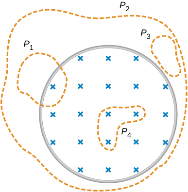
Figure shows the magnetic filed confined within the cylindrical region. Area P1 partially lies in the magnetic field. Area P2 is larger that the area of magnetic field and completely includes it. Area P3 lies outside of the magnetic field. Area P4 is smaller than the area of the magnetic field and is completely included within it.

Answer

P 1 , P 2 , P 4

Check Your Understanding 13.9 §13.4 source ↗

A long solenoid of cross-sectional area 5.0cm2 is wound with 25 turns of wire per centimeter. It is placed in the middle of a closely wrapped coil of 10 turns and radius 25 cm, as shown below. (a) What is the emf induced in the coil when the current through the solenoid is decreasing at a rate dI/dt= −0.20A/s? (b) What is the electric field induced in the coil?
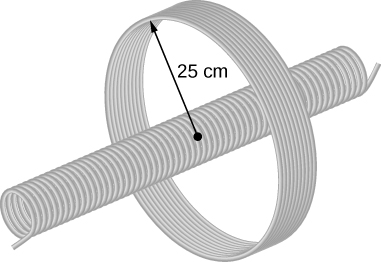
Figure shows a long solenoid placed in the middle of a closely wrapped coil with radius of 25 cm.

Answer

a. 3.1×10⁻⁶V; b. 2.0×10⁻⁷V/m

13-1 §13.1 source ↗

A stationary coil is in a magnetic field that is changing with time. Does the emf induced in the coil depend on the actual values of the magnetic field?

Answer

The emf depends on the rate of change of the magnetic field.

13-3 §13.1 source ↗

A copper ring and a wooden ring of the same dimensions are placed in magnetic fields so that there is the same change in magnetic flux through them. Compare the induced electric fields and currents in the rings.

Answer

Both have the same induced electric fields; however, the copper ring has a much higher induced emf because it conducts electricity better than the wooden ring.

13-5 §13.1 source ↗

(a) Does the induced emf in a circuit depend on the resistance of the circuit? (b) Does the induced current depend on the resistance of the circuit?

Answer

a. no; b. yes

13-7 §13.1 source ↗

Can there be an induced emf in a circuit at an instant when the magnetic flux through the circuit is zero?

Answer

As long as the magnetic flux is changing from positive to negative or negative to positive, there could be an induced emf.

13-9 §13.1 source ↗

How would you position a flat loop of wire in a changing magnetic field so that there is no induced emf in the loop?

Answer

Position the loop so that the field lines run perpendicular to the area vector or parallel to the surface.

13-11 §13.2 source ↗

The circular conducting loops shown in the accompanying figure are parallel, perpendicular to the plane of the page, and coaxial. (a) When the switch S is closed, what is the direction of the current induced in D? (b) When the switch is opened, what is the direction of the current induced in loop D?
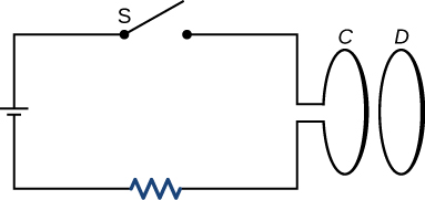
Figure shows a circuit that consists of a resistor, capacitor, opened switch and a loop C. A loop D is located next to the loop C.

Answer

a. CW as viewed from the circuit; b. CCW as viewed from the circuit

13-13 §13.2 source ↗

The accompanying figure shows a conducting ring at various positions as it moves through a magnetic field. What is the sense of the induced emf for each of those positions?
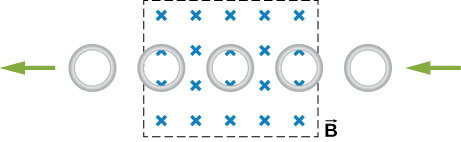
Figure shows the loop that moves through the area with the magnetic field perpendicular to it.

Answer

As the loop enters, the induced emf creates a CCW current while as the loop leaves the induced emf creates a CW current. While the loop is fully inside the magnetic field, there is no flux change and therefore no induced current.

13-15 §13.2 source ↗

State the direction of the induced current for each case shown below, observing from the side of the magnet.
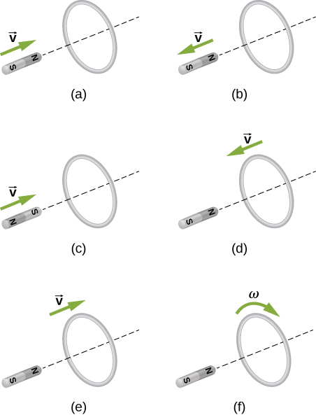
Figure A shows a magnet that is moving towards the loop with the North pole facing the loop. Figure B shows a magnet that is moving away from the loop with the North pole facing the loop. Figure C shows a magnet that is moving towards the loop with the South pole facing the loop. Figure D shows a magnet that is hold constant with the North pole facing the loop. The loop is moving towards the magnet. Figure E shows a magnet that is hold constant with the North pole facing the loop. Loop is moving away from the magnet. Figure F shows a magnet that is hold constant with the North pole facing the loop. Loop is rotating clockwise.

Answer

a. CCW viewed from the magnet; b. CW viewed from the magnet; c. CW viewed from the magnet; d. CCW viewed from the magnet; e. CW viewed from the magnet; f. no current

13-17 §13.3 source ↗

Around the geographic North Pole (or magnetic South Pole), Earth’s magnetic field is almost vertical. If an airplane is flying northward in this region, which side of the wing is positively charged and which is negatively charged?

Answer

Positive charges on the wings would be to the west, or to the left of the pilot while negative charges would be pulled east or to the right of the pilot. Thus, the left hand tips of the wings would be positive and the right hand tips would be negative.

13-19 §13.4 source ↗

Is the work required to accelerate a rod from rest to a speed v in a magnetic field greater than the final kinetic energy of the rod? Why?

Answer

The work is greater than the kinetic energy because it takes energy to counteract the induced emf.

13-21 §13.5 source ↗

A conducting sheet lies in a plane perpendicular to a magnetic field B→ that is below the sheet. If B→ oscillates at a high frequency and the conductor is made of a material of low resistivity, the region above the sheet is effectively shielded from B→. Explain why. Will the conductor shield this region from static magnetic fields?

Answer

The conducting sheet is shielded from the changing magnetic fields by creating an induced emf. This induced emf creates an induced magnetic field that opposes any changes in magnetic fields from the field underneath. Therefore, there is no net magnetic field in the region above this sheet. If the field were due to a static magnetic field, no induced emf will be created since you need a changing magnetic flux to induce an emf. Therefore, this static magnetic field will not be shielded.

13-23 §13.5 source ↗

A coil is moved through a magnetic field as shown below. The field is uniform inside the rectangle and zero outside. What is the direction of the induced current and what is the direction of the magnetic force on the coil at each position shown?
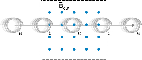
Picture shows a coil is moved from the left to the right through a uniform magnetic field. Magnetic lines are perpendicular to the coil and are directed from the plane of the page.

Answer

a. zero induced current, zero force; b. clockwise induced current, force is to the left; c. zero induced current, zero force; d. counterclockwise induced current, force is to the left; e. zero induced current, zero force.

13-25 §13.1 source ↗

Repeat your calculations of the preceding problem’s time of 0.1 s with the plane of the coil making an angle of (a) 30°, (b) 60°, and (c) 90° with the magnetic field.

Answer

a. 3.8 V; b. 2.2 V; c. 0 V

13-27 §13.1 source ↗

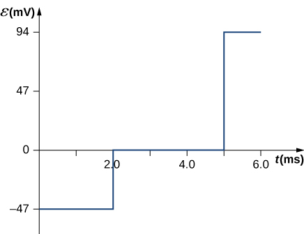
The magnetic field through a circular loop of radius 10.0 cm varies with time as shown below. The field is perpendicular to the loop. Plot the magnitude of the induced emf in the loop as a function of time.
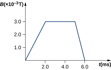
Figure shows the magnetic field in milliTesla plotted as a function of time in ms. Magnetic field is zero when the time is equal to zero. It increases linearly with time reaching 3 milliTesla and 2 ms. It remains the same till 5 ms and then decreases linearly to 0 and 6 ms.

Answer

B=1.5t,0≤t<2.0ms,B=3.0mT,2.0ms≤t≤5.0ms,B=−3.0t+18mT,5.0ms<t≤6.0ms,ε=−dΦmdt=−d(BA)dt=−AdBdt,ε=−π(0.100m)2(1.5T/s)=−47mV(0≤t<2.0ms),ε=π(0.100m)2(0)=0(2.0ms≤t≤5.0ms),ε=−π(0.100m)2(−3.0T/s)=94mV(5.0ms<t<6.0ms).

Figure shows the Emf in mV plotted as a function of time in ms. Emf is equal to -47 mV when the time is equal to zero. It increases in a step fashion to 0 when the time reaches 2 ms. Emf remains the same till 5 ms and then increases in a step fashion to 94 mV. It stays constant till time reaches 6 ms.

13-29 §13.1 source ↗

How would the answers to the preceding problem change if the coil consisted of 20 closely spaced turns?

Answer

Each answer is 20 times the previously given answers.

13-31 §13.1 source ↗

A rectangular wire loop with length a and width b lies in the xy-plane, as shown below. Within the loop there is a time-dependent magnetic field given by B→(t)= C((xcosωt)i^+(ysinωt)k^), with B→(t) in tesla. Determine the emf induced in the loop as a function of time.
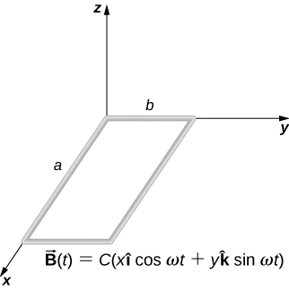
Figure shows a rectangular wire loop with length a and width b lies in the xy-plane.

Answer

n ^ = k ^ , d Φ m = C y sin ( ω t ) d x d y , Φ m = C a b 2 sin ( ω t ) 2 , ε = − C a b 2 ω cos ( ω t ) 2 .

13-33 §13.2 source ↗

A single-turn circular loop of wire of radius 50 mm lies in a plane perpendicular to a spatially uniform magnetic field. During a 0.10-s time interval, the magnitude of the field increases uniformly from 200 to 300 mT. (a) Determine the emf induced in the loop. (b) If the magnetic field is directed out of the page, what is the direction of the current induced in the loop?

Answer

a. 7.8×10⁻³V; b. CCW from the same view as the magnetic field

13-35 §13.2 source ↗

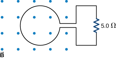
The magnetic flux through the loop shown in the accompanying figure varies with time according to Φm= 2.00e−3tsin(120πt), where Φm is in webers. What are the direction and magnitude of the current through the 5.00-Ω resistor at (a) t=0; (b) t= 2.17×10⁻²s, and (c) t=3.00s?

Figure shows a loop with the magnetic flux perpendicular to the loop. Loop is connected to a 5 Ohm resistor.

Answer

a. 150 A downward through the resistor; b. 46 A upward through the resistor; c. 0.019 A downward through the resistor

13-37 §13.3 source ↗

An automobile with a radio antenna 1.0 m long travels at 100.0 km/h in a location where the Earth’s horizontal magnetic field is 5.5×10⁻⁵T. What is the maximum possible emf induced in the antenna due to this motion?

Answer

0.0015 V

13-39 §13.3 source ↗

Suppose the magnetic field of the preceding problem oscillates with time according to B=B0sinωt. What then is the emf induced in the loop when its trailing side is a distance d from the right edge of the magnetic field region?

Answer

ε= −B0ldωcos(Ωt)ld+ B0sin(Ωt)lv

13-41 §13.3 source ↗

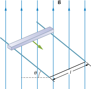
In the circuit shown in the accompanying figure, the rod slides along the conducting rails at a constant velocity v→. The velocity is in the same plane as the rails and directed at an angle θ to them. A uniform magnetic field B→ is directed out of the page. What is the emf induced in the rod?
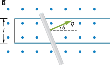
Figure shows the rod that slides along the conducting rails at a constant velocity v in a uniform perpendicular magnetic field. Distance between the rails is l. Angle between the direction of movement of the rod and the rails is theta.

Answer

ε = B l v cos θ

13-43 §13.3 source ↗

A 25-cm rod moves at 5.0 m/s in a plane perpendicular to a magnetic field of strength 0.25 T. The rod, velocity vector, and magnetic field vector are mutually perpendicular, as indicated in the accompanying figure. Calculate (a) the magnetic force on an electron in the rod, (b) the electric field in the rod, and (c) the potential difference between the ends of the rod. (d) What is the speed of the rod if the potential difference is 1.0 V?
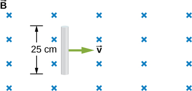
Figure shows the 25 cm long rod of that moves to the right at a constant velocity v in a uniform perpendicular magnetic field.

Answer

a. 2×10⁻¹⁹N; b. 1.25 V/m; c. 0.3125 V; d. 16 m/s

13-45 §13.3 source ↗

The rod shown below moves to the right on essentially zero-resistance rails at a speed of v=3.0m/s. If B=0.75T everywhere in the region, what is the current through the 5.0-Ω resistor? Does the current circulate clockwise or counterclockwise?
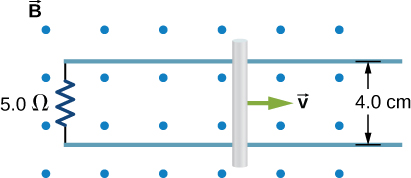
Figure shows the rod that slides to the right along the conducting rails at a constant velocity v in a uniform perpendicular magnetic field. Distance between the rails is 4 cm. The rails are connected through the 5 Ohm resistor.

Answer

0.018 A, CW as seen in the diagram

13-47 §13.4 source ↗

Calculate the induced electric field in a 50-turn coil with a diameter of 15 cm that is placed in a spatially uniform magnetic field of magnitude 0.50 T so that the face of the coil and the magnetic field are perpendicular. This magnetic field is reduced to zero in 0.10 seconds. Assume that the magnetic field is cylindrically symmetric with respect to the central axis of the coil.

Answer

0.1875 V/m

13-49 §13.4 source ↗

The current I through a long solenoid with n turns per meter and radius R is changing with time as given by dI/dt. Calculate the induced electric field as a function of distance r from the central axis of the solenoid.

Answer

Inside, B= μ0nI,∮E→·dl→=(πr2)μ0ndIdt, so, E= μ0nr2·dIdt (inside). Outside, E(2πr)= πR2μ0ndIdt, so, E= μ0nR22r·dIdt (outside)

13-51 §13.4 source ↗

Over a region of radius R, there is a spatially uniform magnetic field B→. (See below.) At t=0, B=1.0T, after which it decreases at a constant rate to zero in 30 s. (a) What is the electric field in the regions where r≤R and r≥R during that 30-s interval? (b) Assume that R=10.0cm. How much work is done by the electric field on a proton that is carried once clock wise around a circular path of radius 5.0 cm? (c) How much work is done by the electric field on a proton that is carried once counterclockwise around a circular path of any radius r≥R? (d) At the instant when B=0.50T, a proton enters the magnetic field at A, moving a velocity v→ (v=5.0×10⁶m/s) as shown. What are the electric and magnetic forces on the proton at that instant?
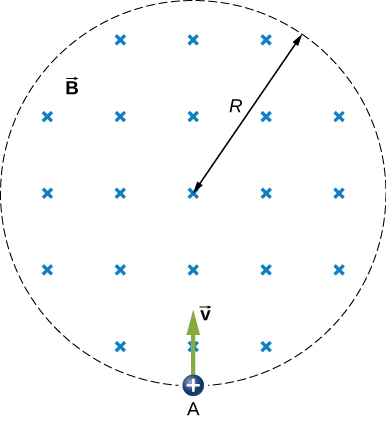
Figure shows a proton carried into a uniform magnetic field with a radius R.

Answer

a. Einside= –r2dBdt, Eoutside= –dBdtR22r; b. W= 4.19×10⁻²³J; c. 0 J; d. Fmag= 4×10⁻¹³N, Felec= 2.7×10⁻²²N

13-53 §13.4 source ↗

The current in a long solenoid with 20 turns per centimeter of radius 3 cm is varied with time at a rate of 2 A/s. A circular loop of wire of radius 5 cm and resistance 2Ω surrounds the solenoid. Find the electrical current induced in the loop.

Answer

7.1 μ A

13-55 §13.6 source ↗

Design a current loop that, when rotated in a uniform magnetic field of strength 0.10 T, will produce an emf ε=ε0sinωt, where ε0=110V and ω= 120πrad/s.

Answer

three turns with an area of 1 m2

13-57 §13.6 source ↗

A 50-turn rectangular coil with dimensions 0.15m×0.40m rotates in a uniform magnetic field of magnitude 0.75 T at 3600 rev/min. (a) Determine the emf induced in the coil as a function of time. (b) If the coil is connected to a 1000-Ω resistor, what is the power as a function of time required to keep the coil turning at 3600 rpm? (c) Answer part (b) if the coil is connected to a 2000-Ω resistor.

Answer

a. ω=120πrad/s,ε=850sin120πt V;
b. P= 720sin2120πtW;
c. P= 360sin2120πtW

13-59 §13.6 source ↗

A flip coil is a relatively simple device used to measure a magnetic field. It consists of a circular coil of N turns wound with fine conducting wire. The coil is attached to a ballistic galvanometer, a device that measures the total charge that passes through it. The coil is placed in a magnetic field B→ such that its face is perpendicular to the field. It is then flipped through 180°, and the total charge Q that flows through the galvanometer is measured. (a) If the total resistance of the coil and galvanometer is R, what is the relationship between B and Q? Because the coil is very small, you can assume that B→ is uniform over it. (b) How can you determine whether or not the magnetic field is perpendicular to the face of the coil?

Answer

a. B is proportional to Q; b. If the coin turns easily, the magnetic field is perpendicular. If the coin is at an equilibrium position, it is parallel.

13-61 §13.6 source ↗

A 120-V, series-wound motor has a field resistance of 80 Ω and an armature resistance of 10 Ω. When it is operating at full speed, a back emf of 75 V is generated. (a) What is the initial current drawn by the motor? When the motor is operating at full speed, where are (b) the current drawn by the motor, (c) the power output of the source, (d) the power output of the motor, and (e) the power dissipated in the two resistances?

Answer

a. 1.33 A; b. 0.50 A; c. 60 W; d. 37.5 W; e. 22.5W

13-63 §13.AP source ↗

Shown in the following figure is a long, straight wire and a single-turn rectangular loop, both of which lie in the plane of the page. The wire is parallel to the long sides of the loop and is 0.50 m away from the closer side. At an instant when the emf induced in the loop is 2.0 V, what is the time rate of change of the current in the wire?
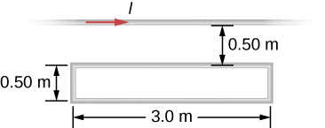
Figure shows a long, straight wire and a single-turn rectangular wire loop with length 3.0 m and width 0.5cm, both of which lie in the plane of the page. The wire is parallel to the long sides of the loop and is 0.50 m away from the closer side.

Answer

4.8 × 10⁶ A/s

13-65 §13.AP source ↗

A current is induced in a circular loop of radius 1.5 cm between two poles of a horseshoe electromagnet when the current in the electromagnet is varied. The magnetic field in the area of the loop is perpendicular to the area and has a uniform magnitude. If the rate of change of magnetic field is 10 T/s, find the magnitude and direction of the induced current if resistance of the loop is 25Ω.

Answer

2.83×10⁻⁴A, the direction as follows for increasing magnetic field:
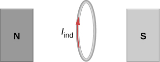
Figure shows a circular loop placed between two poles of a horseshoe electromagnet.

13-67 §13.AP source ↗

A coil with 50 turns and area 10 cm2 is oriented with its plane perpendicular to a 0.75-T magnetic field. If the coil is flipped over (rotated through 180°) in 0.20 s, what is the average emf induced in it?

Answer

0.375 V

13-69 §13.AP source ↗

The conducting rod shown in the accompanying figure moves along parallel metal rails that are 25-cm apart. The system is in a uniform magnetic field of strength 0.75 T, which is directed into the page. The resistances of the rod and the rails are negligible, but the section PQ has a resistance of 0.25Ω. (a) What is the emf (including its sense) induced in the rod when it is moving to the right with a speed of 5.0 m/s? (b) What force is required to keep the rod moving at this speed? (c) What is the rate at which work is done by this force? (d) What is the power dissipated in the resistor?
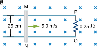
Figure shows the rod that slides to the right along the conducting rails at a constant velocity 5 meters per second in a uniform perpendicular magnetic field. Distance between the rails is 25 cm. The rails are connected trough the 0.25 Ohm resistor.

Answer

a. 0.94 V; b. 0.70 N; c. 3.52 J/s; d. 3.52 W

13-71 §13.AP source ↗

The magnetic field between the poles of a horseshoe electromagnet is uniform and has a cylindrical symmetry about an axis from the middle of the South Pole to the middle of the North Pole. The magnitude of the magnetic field changes as a rate of dB/dt due to the changing current through the electromagnet. Determine the electric field at a distance r from the center.

Answer

( d B d t ) A 2 π r

13-73 §13.AP source ↗

A 120-V, series-wound dc motor draws 0.50 A from its power source when operating at full speed, and it draws 2.0 A when it starts. The resistance of the armature coils is 10Ω. (a) What is the resistance of the field coils? (b) What is the back emf of the motor when it is running at full speed? (c) The motor operates at a different speed and draws 1.0 A from the source. What is the back emf in this case?

Answer

a. Rf+ Ra= 120V2.0A= 60Ω, soRf= 50Ω;
b. I= εs−εiRf+Ra, ⇒εi= 90V;
c. εi=60V

13-75 §13.CP source ↗

A copper wire of length L is fashioned into a circular coil with N turns. When the magnetic field through the coil changes with time, for what value of N is the induced emf a maximum?

Answer

N = 1

13-77 §13.CP source ↗

A circular copper disk of radius 7.5 cm rotates at 2400 rpm around the axis through its center and perpendicular to its face. The disk is in a uniform magnetic field B→ of strength 1.2 T that is directed along the axis. What is the potential difference between the rim and the axis of the disk?

Answer

0.848 V

13-79 §13.CP source ↗

A rectangular circuit containing a resistance R is pulled at a constant velocity v→ away from a long, straight wire carrying a current I0 (see below). Derive an equation that gives the current induced in the circuit as a function of the distance x between the near side of the circuit and the wire.
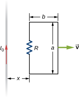
Figure shows a rectangular circuit containing a resistor R that is pulled at a constant velocity v away from a long, straight wire carrying a current I0. Circuit is currently located at a distance x from the wire. Long side of the circuit is of the length a. It is parallel to the wire and contains the resistor. Short side of the circuit is of the length b.

Answer

Φ = μ 0 I 0 a 2 π ln ( 1 + b x ) , ε = μ 0 I 0 a b v 2 π x ( x + b ) , so I = μ 0 I 0 a b v 2 π R x ( x + b )

13-81 §13.CP source ↗

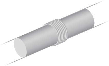
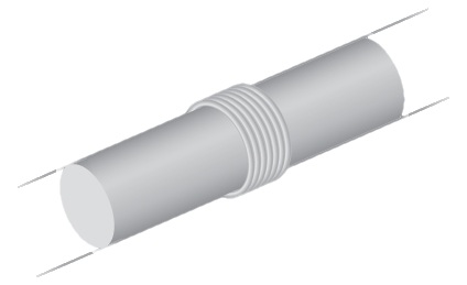
An eight-turn coil is tightly wrapped around the outside of the long solenoid as shown below. The radius of the solenoid is 2.0 cm and it has 10 turns per centimeter. The current through the solenoid increases according to I= I0(1−e−αt), where I0=4.0A and α= 2.0×10⁻²s−1. What is the emf induced in the coil when (a) t=0, (b) t=1.0×10²s, and (c) t→∞?

Figure shows a coil that is tightly wrapped around the outside of the long solenoid.Figure shows a coil that is tightly wrapped around the outside of the long solenoid.

Answer

a. 1.01×10⁻⁶V; b. 1.37×10⁻⁷V; c. 0 V

13-83 §13.CP source ↗

A square bar of mass m and resistance R is sliding without friction down very long, parallel conducting rails of negligible resistance (see below). The two rails are a distance l apart and are connected to each other at the bottom of the incline by a zero-resistance wire. The rails are inclined at an angle θ, and there is a uniform vertical magnetic field B→ throughout the region. (a) Show that the bar acquires a terminal velocity given by v= mgRsinθB2l2cos2θ. (b) Calculate the work per unit time done by the force of gravity. (c) Compare this with the power dissipated in the Joule heating of the bar. (d) What would happen if B→ were reversed?

Figure shows a square sliding down very long, parallel conducting rails. The two rails are a distance l apart and are inclined at an angle theta. There is a uniform vertical magnetic field B throughout the region.

Answer

a. v= mgRsinθB2l2cos2θ; b. mgvsinθ; c. mcΔT; d. current would reverse direction but bar would still slide at the same speed

13-85 §13.CP source ↗

A long solenoid with 10 turns per centimeter is placed inside a copper ring such that both objects have the same central axis. The radius of the ring is 10.0 cm, and the radius of the solenoid is 5.0 cm. (a) What is the emf induced in the ring when the current I through the solenoid is 5.0 A and changing at a rate of 100 A/s? (b) What is the emf induced in the ring when I=2.0A and dI/dt= 100A/s? (c) What is the electric field inside the ring for these two cases? (d) Suppose the ring is moved so that its central axis and the central axis of the solenoid are still parallel but no longer coincide. (You should assume that the solenoid is still inside the ring.) Now what is the emf induced in the ring? (e) Can you calculate the electric field in the ring as you did in part (c)?

Answer

a.
B=μ0nI,Φm=BA=μ0nIA,ε=9.9×10⁻⁴V;
b. 9.9×10⁻⁴V;
c. ∮E→·dl→= ε, ⇒E= 1.6×10⁻³V/m; d. 9.9×10⁻⁴V;
e. no, because there is no cylindrical symmetry

13-87 §13.CP source ↗

A 500-turn coil with a 0.250-m2 area is spun in Earth’s 5.00×10⁻⁵T magnetic field, producing a 12.0-kV maximum emf. (a) At what angular velocity must the coil be spun? (b) What is unreasonable about this result? (c) Which assumption or premise is responsible?

Answer

a. 1.92×10⁶rad/s= 1.83×10⁷rpm; b. This angular velocity is unreasonably high, higher than can be obtained for any mechanical system. c. The assumption that a voltage as great as 12.0 kV could be obtained is unreasonable.

13-89 §13.CP source ↗

A long solenoid of radius a with n turns per unit length is carrying a time-dependent current I(t)= I0sinωt where I0 and ω are constants. The solenoid is surrounded by a wire of resistance R that has two circular loops of radius b with b>a. Find the magnitude and direction of current induced in the outer loops at time t=0.

Answer

2 μ 0 π a 2 I 0 n ω R

13-91 §13.CP source ↗

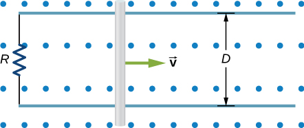
A metal bar of mass m slides without friction over two rails a distance D apart in the region that has a uniform magnetic field of magnitude B0 and direction perpendicular to the rails (see below). The two rails are connected at one end to a resistor whose resistance is much larger than the resistance of the rails and the bar. The bar is given an initial speed of v0. It is found to slow down. How far does the bar go before coming to rest? Assume that the magnetic field of the induced current is negligible compared to B0.

Figure shows metal bar that slides over two rails a distance D apart in the region that has a uniform magnetic field of magnitude in direction perpendicular to the rails. The two rails are connected at one end to a resistor R.

Answer

m R v o B 2 D 2

Loading chapter 14…

Problems and answers are adapted from University Physics Volume 2 by Samuel J. Ling, Jeff Sanny and William Moebs, OpenStax, and are used under the CC BY-NC-SA 4.0 licence. Access for free at https://openstax.org/books/university-physics-volume-2/pages/1-introduction. Illustrations: Copyright Rice University, OpenStax, under CC BY-NC-SA 4.0 license. This adaptation is released under the same licence, is non-commercial, and is neither affiliated with nor endorsed by OpenStax or Rice University.